Laminate cased battery

Active Publication Date: 2007-09-27
SANYO ELECTRIC CO LTD
View PDF1 Cites 8 Cited by
  • Summary
  • Abstract
  • Description
  • Claims
  • Application Information

AI Technical Summary

Benefits of technology

[0071] The battery 1 in the present embodiment, which has the above-described structure and is made by the above-described manufacturing method, has the following advantages.
[0072] In the outer casing 10 of the battery 1 of the present embodiment, as indicated by Equations 1 and 2, the curvature radiuses RB and RD of the corners on the bottom side are set to be larger than the curvature radiuses RA and RC of the corners on the top side. With this structure, it is possible to reduce the stresses applied to the corners where the side surface 10g and the side surface 10f meet each other and the side surface 10g and the side surface 10h meet each other on the bottom side, and the main surface 10a and the side surface 10g meet each other, when the dent 101a is formed in the metal laminate sheet 100.
[0073] Further, in the present embodiment, the curvature radius RE of the corners where the side surface 10f and the main surface 10a meet each other and the side surface 10h and the main surface 10a meet each other, is set as indicated by Equation 3. This is more advantageous in terms of reducing the stresses that are generated when the dent 101a is formed.
[0074] In the battery 1 of the present embodiment, all the curvature radiuses at the corners where the surfaces, including those on the top side, meet each other are increased uniformly. That is to say, the curvature radiuses RB and RD of the corners on the bottom side are set to be larger since this is required in terms

Problems solved by technology

However, in the laminate cased batteries with such a structure, when the dent is formed in the laminate sheet, pin holes or cracks often occur at corners of the dent in the laminate outer casing.
It is though

Method used


Image

  • Laminate cased battery
  • Laminate cased battery
  • Laminate cased battery

Examples


cased battery

1. Structure of Laminate Cased Battery

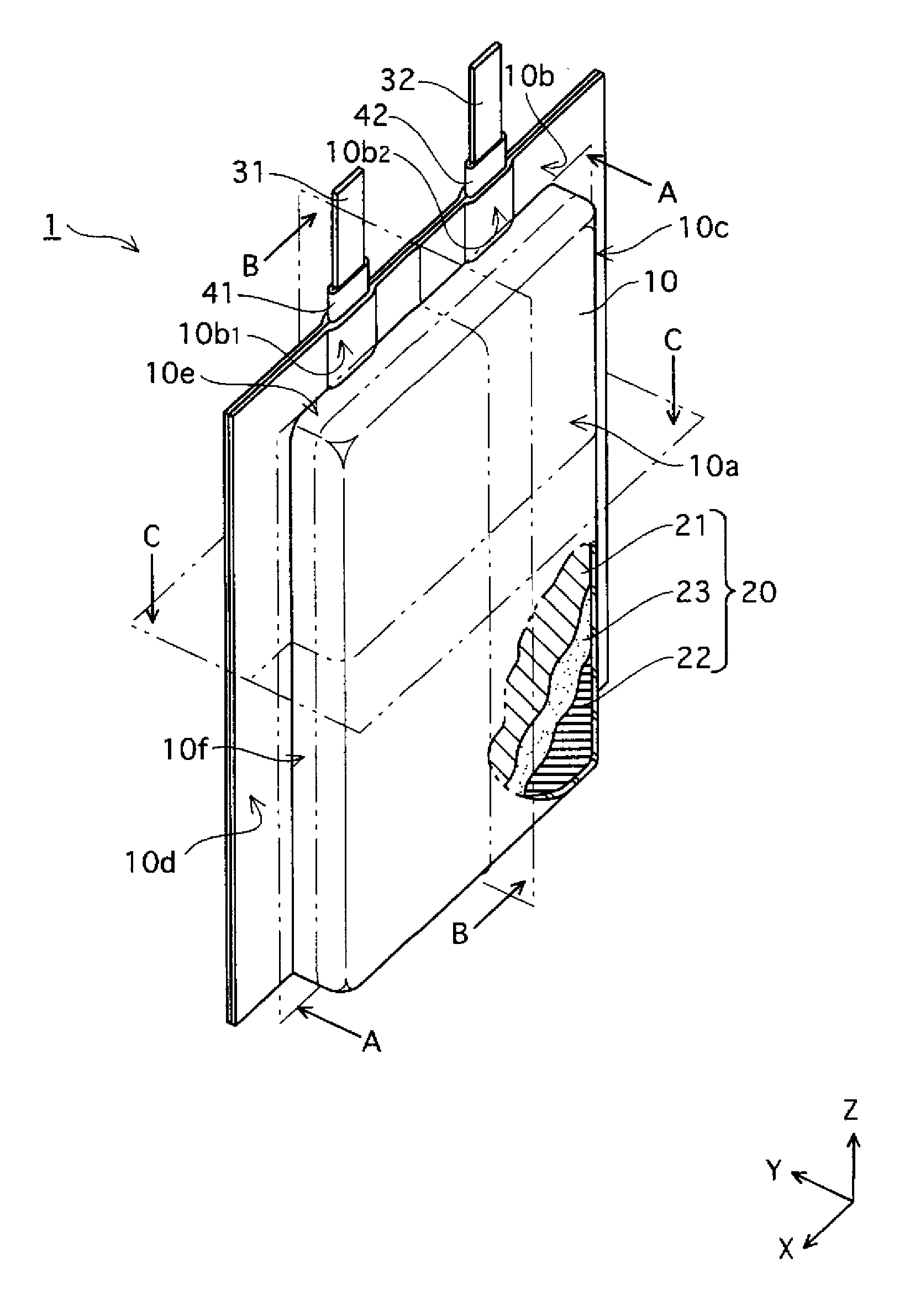
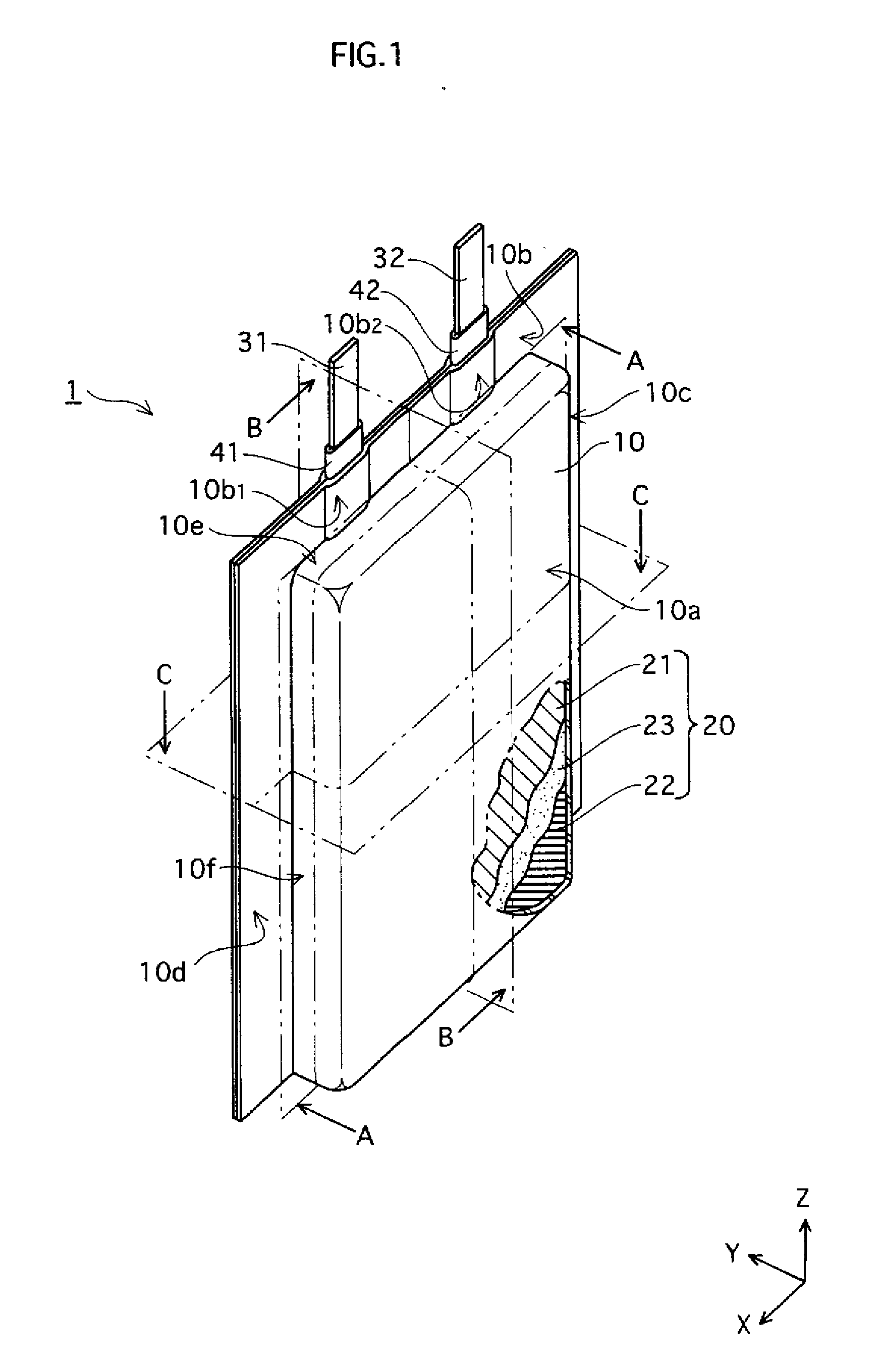
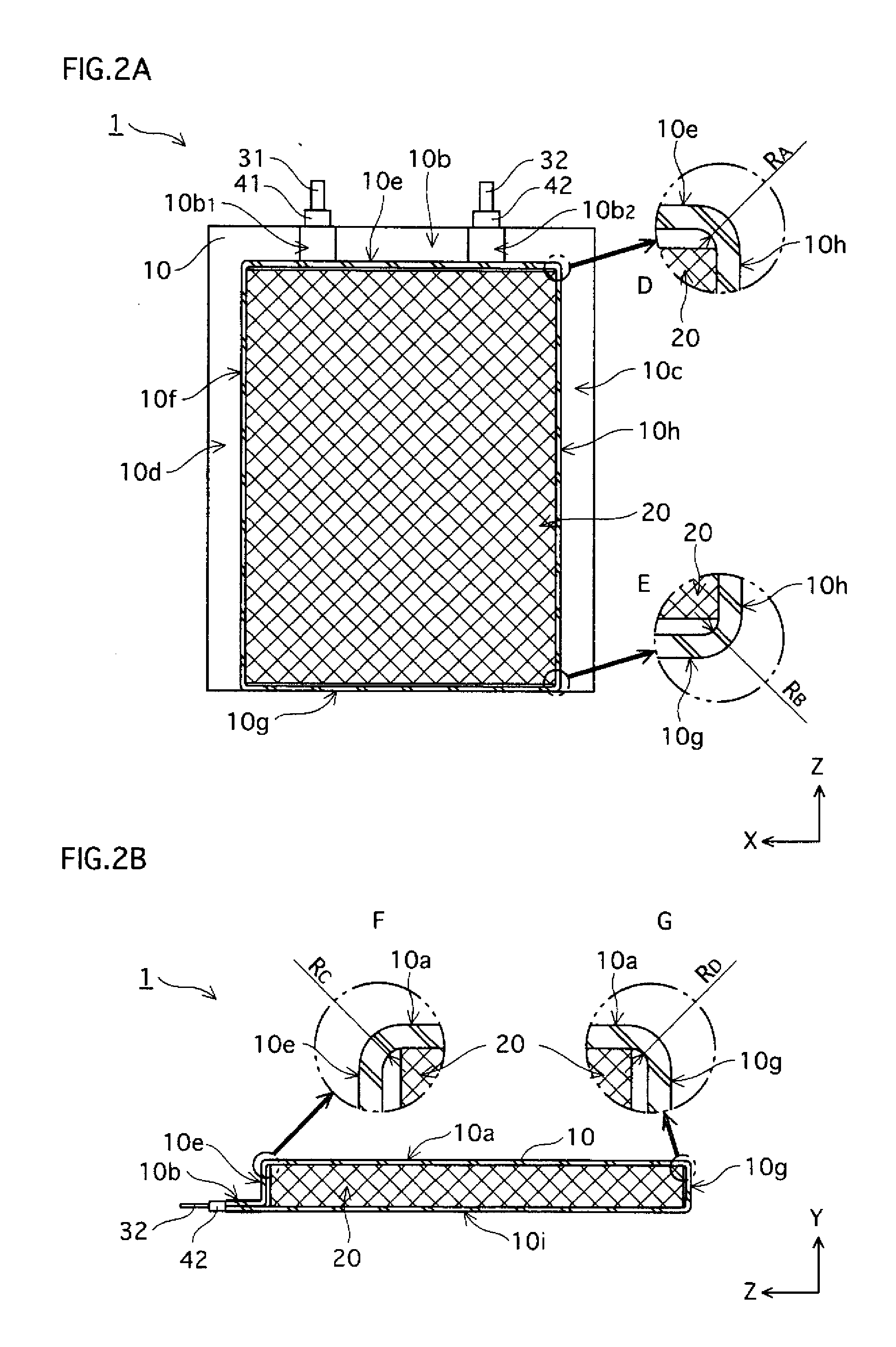
[0034] The structure of a laminate cased battery (hereinafter merely referred to as “battery”) 1 of the present embodiment will be described with reference to FIGS. 1, 2A, and 2B.

[0035] As shown in FIG. 1, the battery 1 has a structure in which an electrode assembly 20 is housed in an inner space of an outer casing 10, which is made from one sheet of metal laminate and has been sealed at three side edges 10b, 10c, and 10d thereof. The electrode assembly 20 is formed by arranging a positive electrode plate 21 and a negative electrode plate 22 to face each other with a separator 23 therebetween, and winding the set of these members. Tabs 31 and 32 are connected to the positive electrode plate 21 and the negative electrode plate 22, respectively. The tabs 31 and 32 are extended out upward from the outer casing 10 to cross the side edge 10b that is on the upper side of the outer casing 10 in the Z axis direction shown in FIG. 1.

[0036] The tab 31 i...


PUM


Abstract

A laminate cased battery in which at least one of curvature radiuses RB and RD of the corners (bottom side corners) where the first side surface respectively meets the second main surface, the third side surface and the fourth side surface is set to be larger than at least one of curvature radiuses RA and RC of the corners (top side corners) where the second side surface respectively meets the second main surface, the third side surface and the fourth side surface.

Description

BACKGROUND OF THE INVENTION [0001] (1) Field of the Invention [0002] The present invention relates to a laminate cased battery including an outer casing made from a sheet of metal laminate, and more specifically, to the shape of the outer casing. [0003] (2) Description of the Related Art [0004] In recent years, portable machines such as mobile phones have become prevalent. In such portable machines, batteries are widely used as the power sources. Among those batteries, lithium polymer batteries with laminate outer casings (hereinafter referred to as “laminate cased batteries”), which have an advantage of being lightweight and having high energy density, are adopted in many types of portable machines. [0005] The laminate cased batteries are formed by housing an electrode assembly, which includes a positive electrode plate, a negative electrode plate and a separator, into a dent that has been formed by executing a punch working on a sheet of metal laminate, bending the sheet so that a...

Claims


Application Information

Patent Timeline
IPC IPC(8): H01M2/00H01M10/05H01M10/058H01M50/126H01M50/178H01M50/55H01M50/557H01M50/562
CPCH01M2/021H01M2/0212H01M2/0285H01M2/0275H01M2/0217Y02E60/10H01M50/557H01M50/103Y02P70/50H01M50/126H01M50/562H01M50/55H01M50/178
Inventor KODAMA, YASUNOBUOKUDA, KAZUHIRO
Owner SANYO ELECTRIC CO LTD
Why Eureka
Try Eureka