Drive system for imaging device

a drive system and imaging device technology, applied in the field of imaging devices, can solve the problems of screw drive mechanism friction and wear, overheating and failure of the front bearing, and the driving system overloads the front bearing, etc., to achieve the effect of simple, compact, reliable and accurate drive system, and simple and effective way

Active Publication Date: 2007-10-04
GENERAL ELECTRIC CO
View PDF11 Cites 9 Cited by
  • Summary
  • Abstract
  • Description
  • Claims
  • Application Information

AI Technical Summary

Benefits of technology

[0006] In another embodiment, the invention provides a simple, compact, reliable and accurate drive system for an imaging device. The drive system comprises a table assembly and a driving system. The driving system is coupled to the table assembly. The table assembly comprises a carrier and two or more elongated rails placed beneath the carrier. The driving system comprises one or more double end shaft motors. A single double end shaft motor is used along with other support accessories in a simple and effective way. The driving system further comprises one or more belts driven by the double end shaft motor. The double end shaft motor is coupled to the belt by means of a coupling device. Two or more timer pulleys are mounted on the double end shaft motor to drive the belt. The timer pulleys are positive drive elements that are coupled to a feedback device and a brake device at each end. The feedback device provides a greater positioning accuracy. The brake device provides a better safety and imparts a robust design feature to the driving system. The driving system imparts a similar function as a screw drive mechanism with an increased flexibility and an enhanced motor life.

Problems solved by technology

Due to overhang leverage and cantilever behavior of the single end shaft motor, the driving system overloads the front bearing.
The overload can lead to overheating and failure of the front bearing.
The screw drive mechanism has an issue of friction and wear.
Moreover, the single end shaft motor used in the screw drive system has an issue of over hang load, which cannot be resolved unless a higher size motor is used.
The primary limitation in the screw drive mechanism is that, the alignment between the linear guides and the driving screw is critical to the quality (CTQ).

Method used


Image

  • Drive system for imaging device
  • Drive system for imaging device
  • Drive system for imaging device

Examples


Embodiment Construction

[0014] In the following detailed description, reference is made to the accompanying drawings that form a part hereof, and in which is shown by way of illustration specific embodiments, which may be practiced. These embodiments are described in sufficient detail to enable those skilled in the art to practice the embodiments, and it is to be understood that other embodiments may be utilized and that logical, mechanical, electrical and other changes may be made without departing from the scope of the embodiments. The following detailed description is, therefore, not to be taken in a limiting sense.

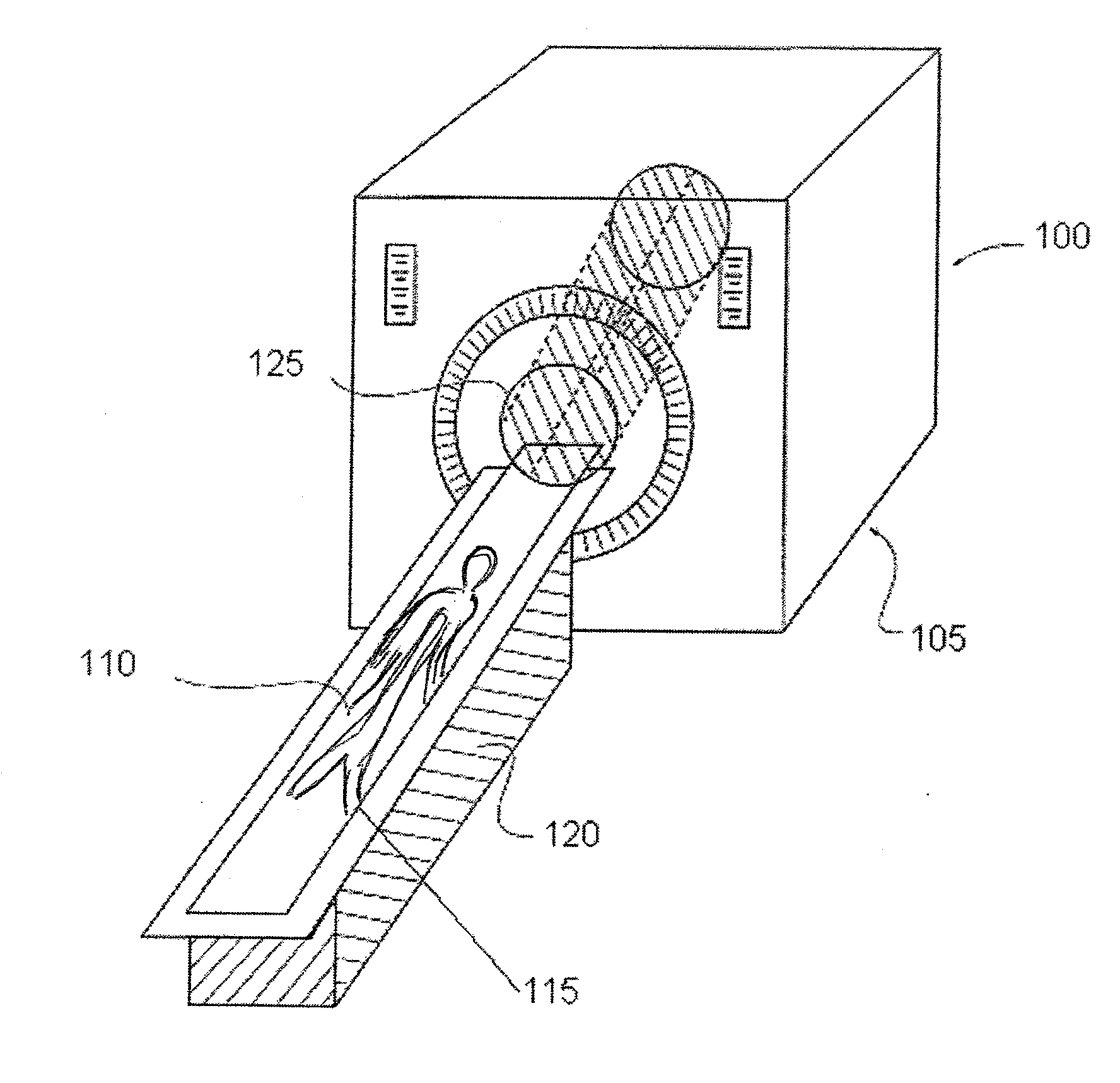
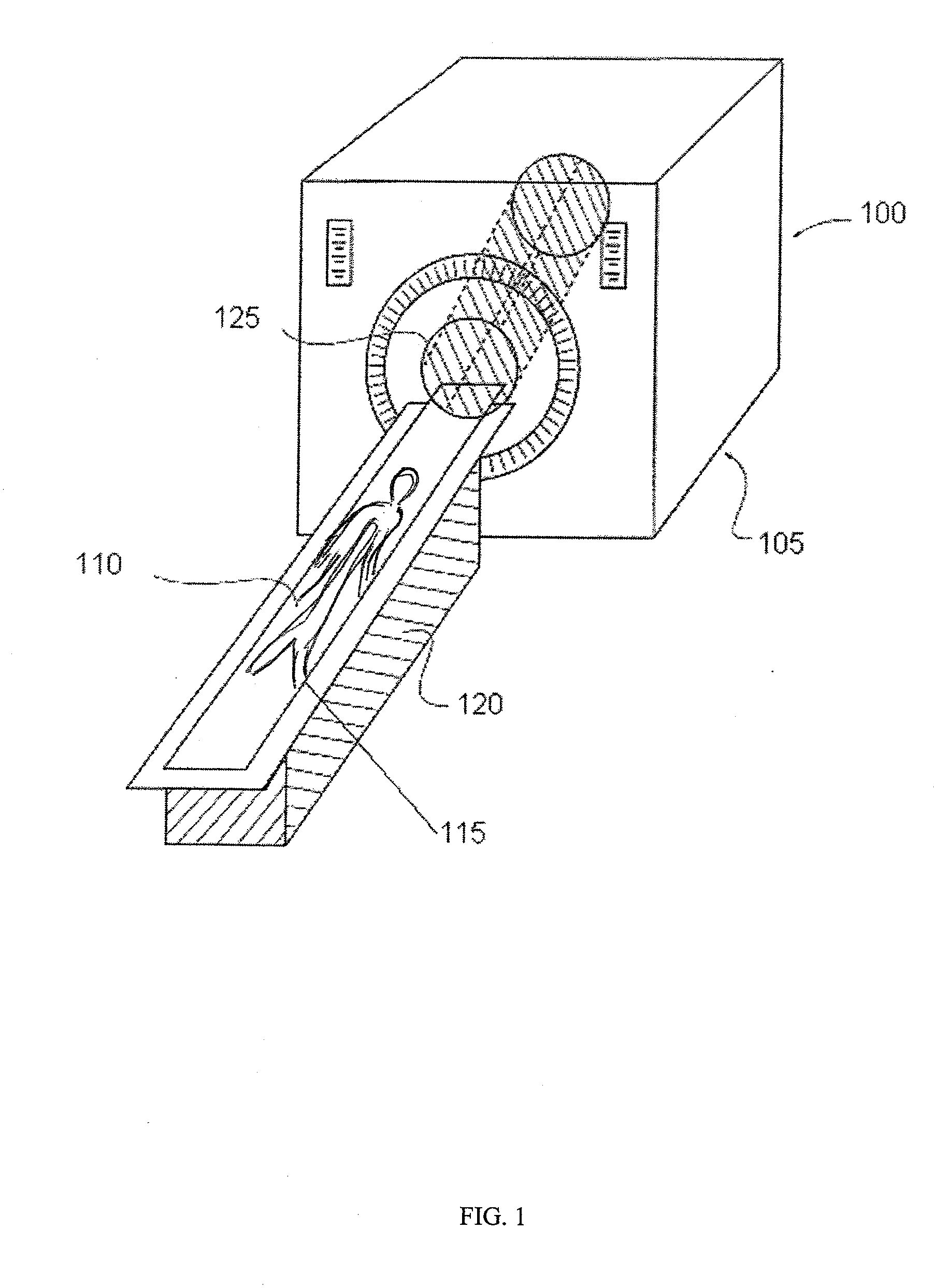
[0015] In various embodiments of the invention, a drive system for an imaging device and an imaging device using a drive system are described. However, the embodiments are not limited and may be implemented in connection with different applications. The application of the invention can be extended to other areas, for example positioning devices. The invention provides a broad concept of a ro...


PUM


Abstract

A drive system for an imaging device is provided. The drive system comprises a table assembly for engaging and supporting a patient and a driving system for moving the table assembly. The driving system can be directly coupled to the table assembly. The table assembly comprises a carrier that engages and supports a patient and at least two elongated rails placed beneath the carrier and extending between the opposing sides of the table assembly. The driving system for moving the table assembly comprises at least one double end shaft motor, at least one belt coupled to the double end shaft motor via a coupling device and at least one pair of timer pulleys coupled to the belt. Further, each timer pulley is directly coupled to a feedback device at a first end and a brake device at a second end.

Description

FIELD OF INVENTION [0001] This invention relates generally to an imaging device and more particularly to a patient positioning system in an imaging device. BACKGROUND OF THE INVENTION [0002] Patient positioning systems are used by imaging devices to position patients with respect to an imaging system of the imaging device. For example, computed tomography (CT) imaging systems typically include a patient positioning system including a table upon which the patient lies and a drive system to move the table (and hence the patient) as the patient is scanned by the CT imaging system. A conventional drive system in an imaging device comprises a driving system to convert a rotary motion to a linear motion. The driving system uses one of a screw drive mechanism and a friction drive mechanism to convert a rotary motion to the linear motion. The screw drive mechanism comprises a driving screw and one or more linear guides. The linear guides are linear motion bearings that bear loads to guide t...

Claims


Application Information

Patent Timeline
Patent Type & Authority Applications(United States)
IPC IPC(8): A61G7/10
CPCA61B6/0457A61B6/0487
Inventor FAROOQUI, ASGHAR ALI
Owner GENERAL ELECTRIC CO
Why Eureka
Try Eureka