Combustor

a combustor and combustor technology, applied in the field of improved combustor, can solve the problems of low and create visible or invisible smoke and emissions in combustor exhaust gases

Active Publication Date: 2007-10-04
PRATT & WHITNEY CANADA CORP
View PDF20 Cites 39 Cited by
  • Summary
  • Abstract
  • Description
  • Claims
  • Application Information

AI Technical Summary

Benefits of technology

[0005] In another aspect, the present invention provides a combustor for a gas turbine engine comprising a liner having annular outer and inner walls defining an annular chamber therebetween, a plurality of circumferentially spaced fuel nozzle holes defined in the liner for in

Problems solved by technology

Nevertheless, prior art means do not always result in low smoke and emissions in combustor exhaust gases.
Under the pressure differential existing in a combu

Method used


Image

  • Combustor
  • Combustor
  • Combustor

Examples


Embodiment Construction

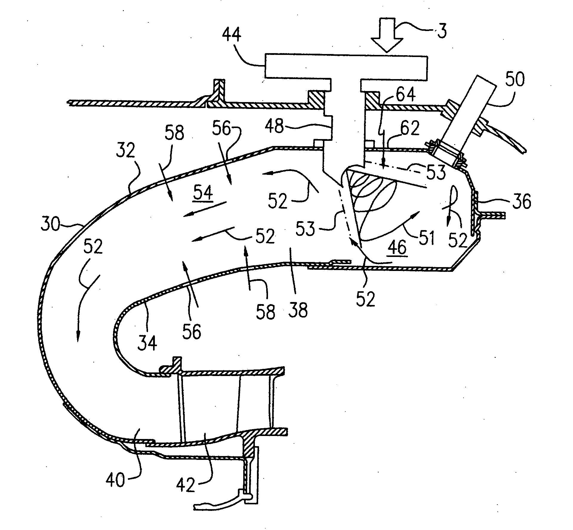
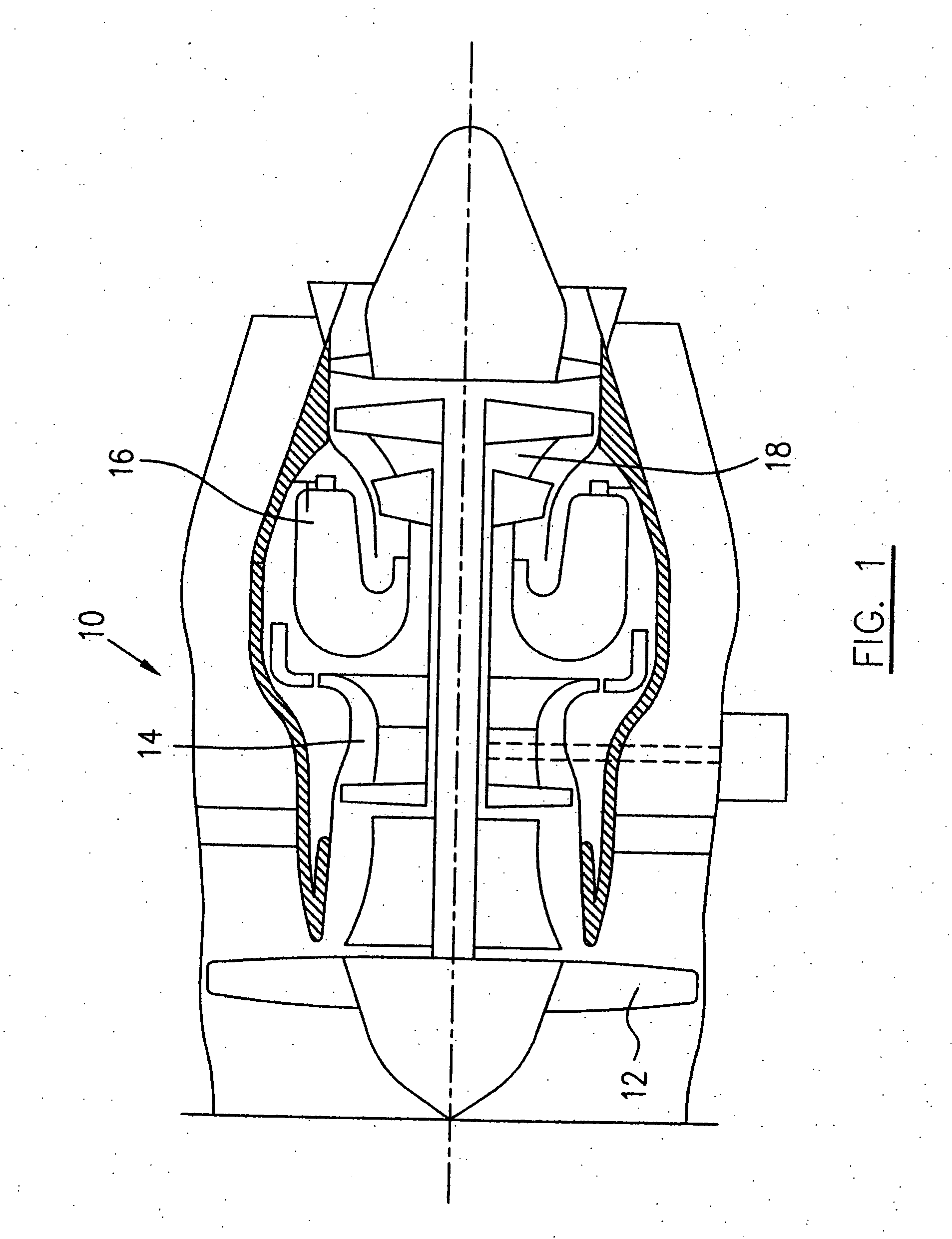
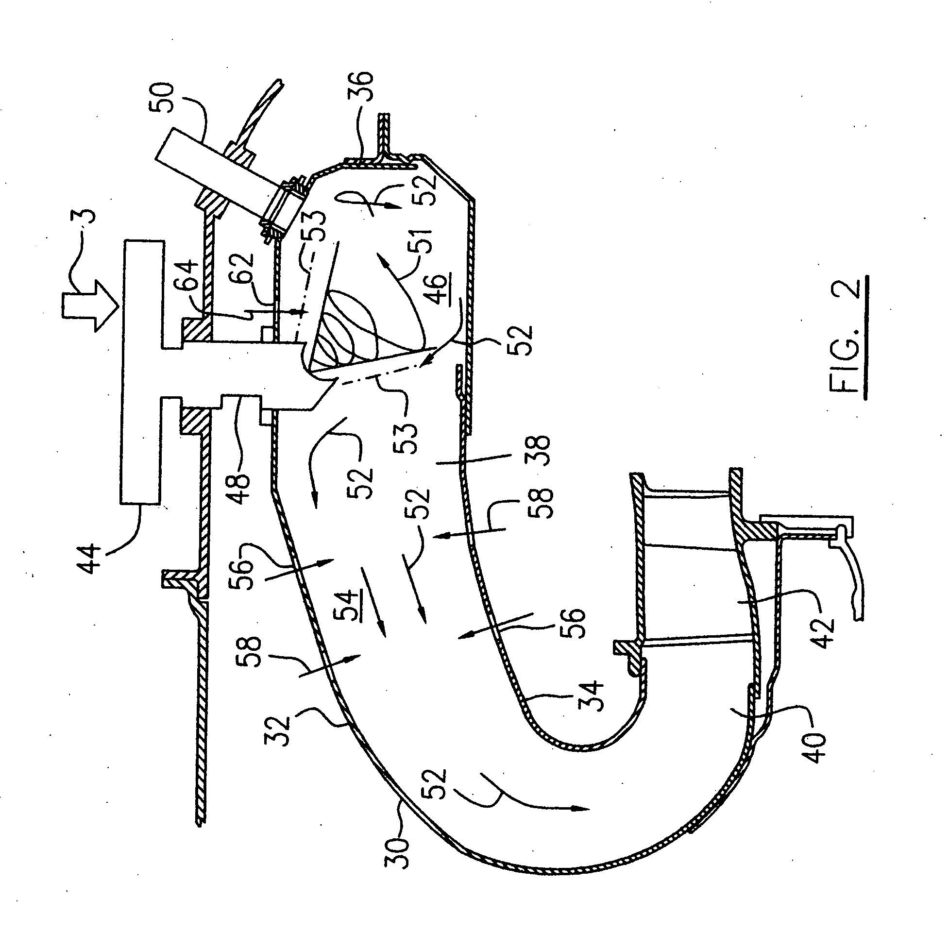
[0015] A turbo fan engine 10 illustrated schematically in FIG. 1, presented as an example of the application of the present invention, includes a spool assembly which includes a fan 12, a compressor section 14, and a turbine assembly 18. A casing surrounds the spool assembly to define a main fluid path (not indicated) therethrough. In the main fluid path there is provided a combustor 16 with fuel injecting means (not indicated) to constitute a gas generator section. In this figure, a reverse flow annular combustor is shown in a turbofan, although it will be recognized that a variety of combustor configurations are available for use in with the present invention, and may be provided in turbofans, turboprops, turboshafts or auxiliary power unit gas turbines. The fan 12 and compressor 14 drive a main airflow (not indicated) along the main fluid path to take part and support a combustion reaction within the combustor 16. Combustion gases are discharged from the combustor 16 to power the...


PUM


Abstract

A combustor is provided having one or more apertures adapted to asymmetrically introduce air adjacent the fuel nozzles to reduce smoke resulting from unburned hydrocarbons in a gas turbine engine combustion system by impeding escape of unburned hydrocarbons.

Description

TECHNICAL FIELD [0001] The invention relates generally to gas turbine engines, and, more particularly, to an improved combustor for gas turbine engines. BACKGROUND OF THE ART [0002] Commercial aircraft gas turbine engines must meet certain federally-mandated smoke and emissions requirements. The prior art includes various means for reducing gas turbine engine exhaust emissions and smoke, for example through more fully mixing and atomizing fuel and air in order to obtain more complete combustion. Nevertheless, prior art means do not always result in low smoke and emissions in combustor exhaust gases. Under the pressure differential existing in a combustor chamber, some unburned fine fuel droplets escape to the combustor, thereby creating visible or invisible smoke and emissions in combustor exhaust gases. Accordingly, there is a need to provide improved low smoke and emissions combustor to avoid the shortcomings of the prior art. SUMMARY OF THE INVENTION [0003] It is therefore an obj...

Claims


Application Information

Patent Timeline
IPC IPC(8): F23R3/06
CPCF23R3/04F23R3/06Y02T50/675F23R2900/03041F23R2900/03044F23R3/54Y02T50/60
Inventor ALKABIE, HISHAMMCCALDON, KIAN
Owner PRATT & WHITNEY CANADA CORP
Why Eureka
Try Eureka