Automatic pattern making apparatus

US20070227332A1Inactive Publication Date: 2007-10-04ESSELTE LLC

Image

  • Automatic pattern making apparatus
  • Automatic pattern making apparatus
  • Automatic pattern making apparatus

Examples


Embodiment Construction

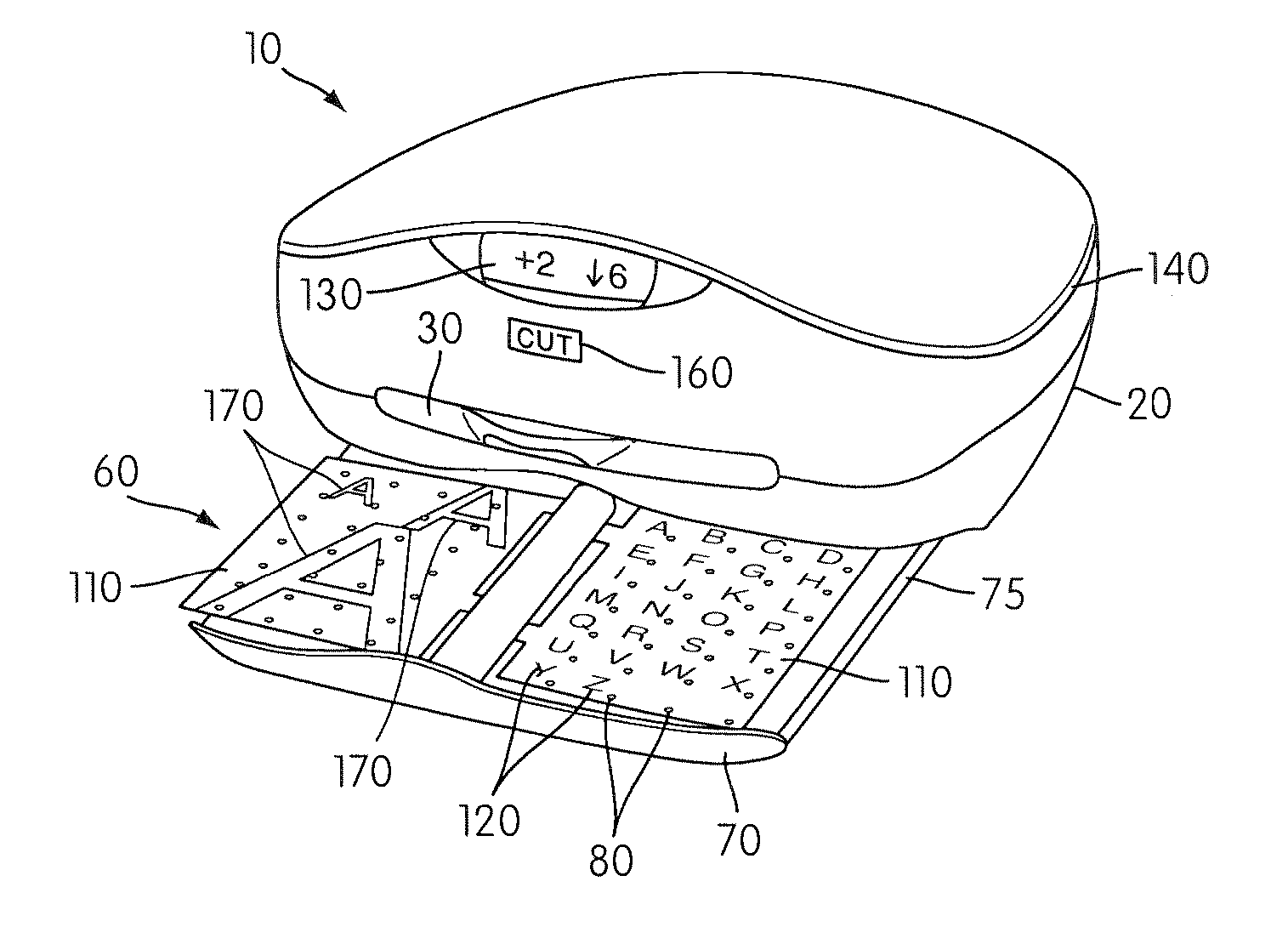
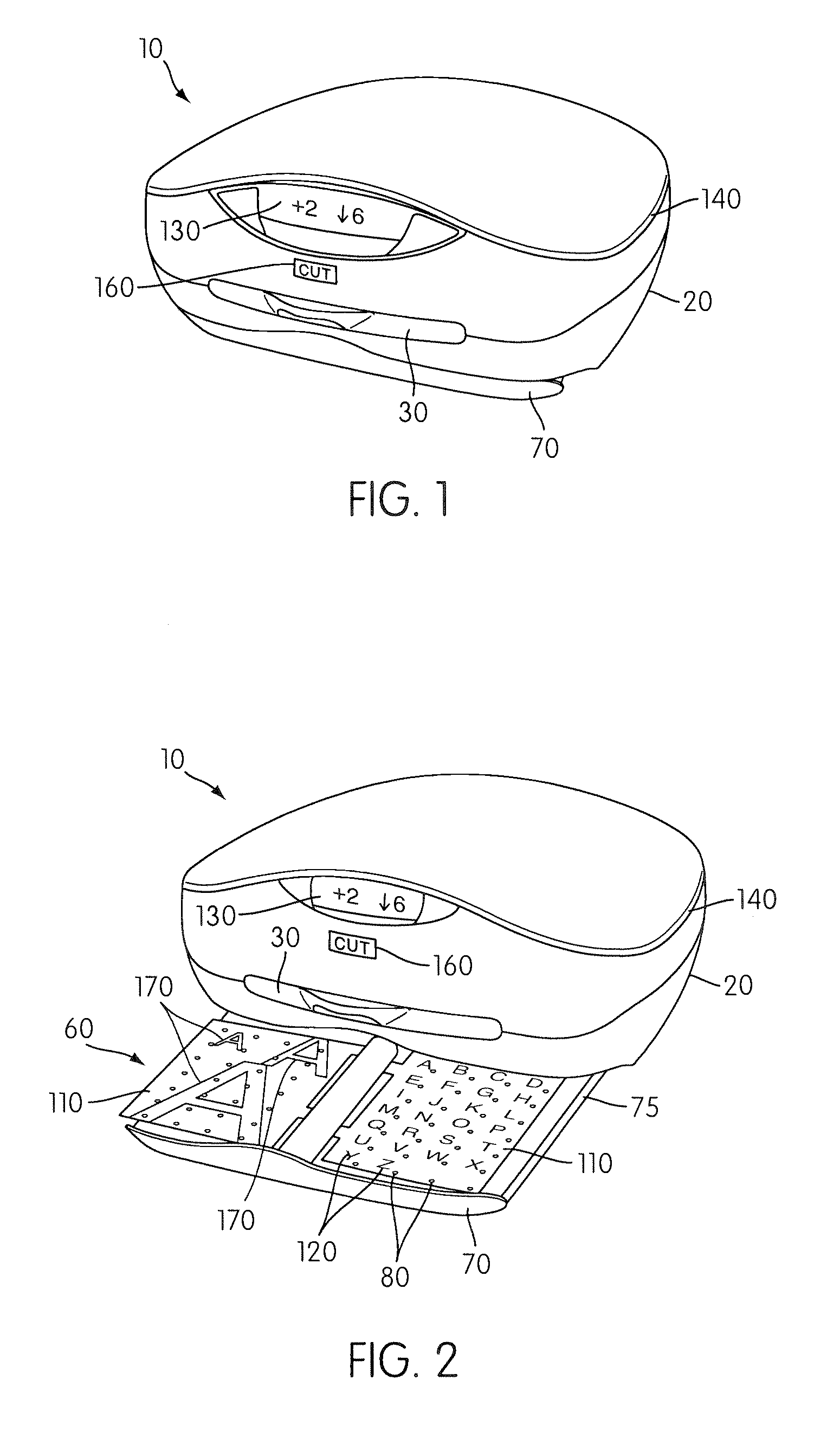
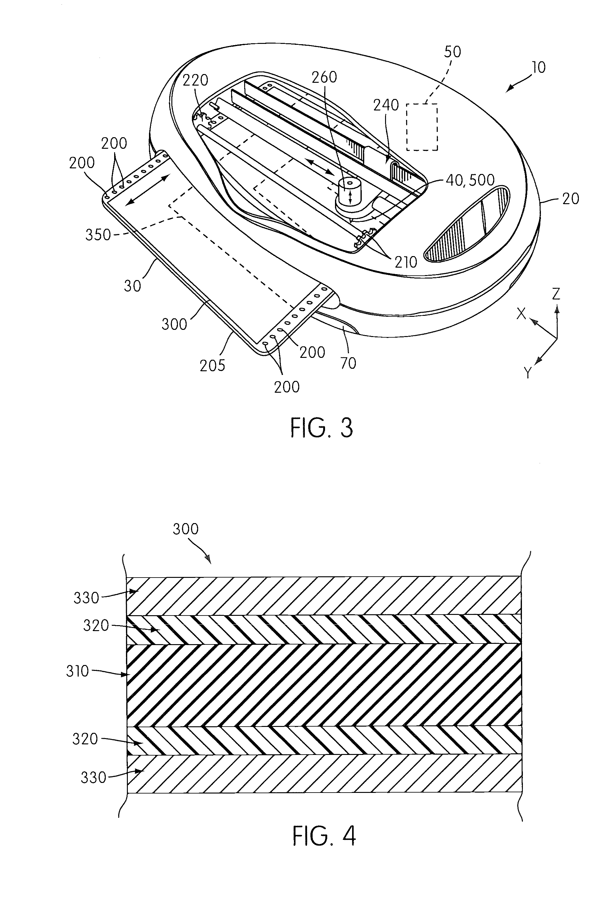
[0058]FIGS. 1-3 illustrate an automatic pattern cutting apparatus 10 according to one embodiment of the present invention. The apparatus 10 comprises a housing 20, a cutting / work piece supporting platform 30 mounted to the housing 20, and a work piece cutter 40 (see FIG. 3). The cutter 40 is movably mounted to the housing 20 to permit the cutter 40 to move relative to the cutting platform 30 in generally orthogonal X and Z directions, and the platform 30 is movable relative to the cutter 40 in a Y direction, which is generally orthogonal to both the X and Z directions. A cutter controller 50 operatively connects to the cutter 40 and the platform 30 to move the cutter 40 and the platform 30 relative to one another in the X, Y, and Z directions. The platform 30, cutter 40, and cutter controller 50, as well as alternative constructions, are discussed later in the application. The apparatus 10 also includes an interchangeable pattern booklet 60 (see FIG. 2) that removably engages an ope...


PUM

PropertyMeasurementUnit
Lengthaaaaaaaaaa
Forceaaaaaaaaaa
Forceaaaaaaaaaa

Abstract

An automatic paper cutting apparatus includes an X-Y cutter, a cutter controller, and a pattern booklet. The pattern booklet includes a plurality of pattern identifiers and a memory device with cutting instructions for each of the identified patterns. The booklet removably mounts to the cutter controller so that an operator can select a pattern from the pattern booklet and have the memory device provide the corresponding set of cutting instructions to the cutter controller. The cutter controller uses the instructions to control the X-Y cutter and cut the desired pattern. A cutting platform of the X-Y cutter has a tacky adhesive that releaseably secures a work piece to the cutting platform during cutting operations. The cutting platform includes surface features that engage a spur gear. The cutter controller selectively rotates the spur gear to drive the cutting platform in the Y direction. The apparatus may use a journaling, embossing, perforating instrument instead of the cutter to make a pattern on the work piece.

Description

CROSS REFERENCE [0001] This application is a continuation-in-part of U.S. Utility application Ser. No. 11 / 272,295, titled “Automatic Pattern Making Apparatus,” filed Nov. 14, 2005, which claims the benefit of priority from U.S. Provisional Application No. 60 / 627,179, titled “Automatic Pattern Making Apparatus,” filed Nov. 15, 2004. This application also claims the benefit of priority from U.S. Provisional Application No. 60 / 763,888, titled “Automatic Pattern Making Apparatus,” filed Feb. 1, 2006. This application also claims the benefit of priority from U.S. Provisional Application No. 60 / 886,767, titled “Automatic Pattern Making Apparatus,” filed Jan. 26, 2007. The entire contents of all of these applications are incorporated herein by reference.BACKGROUND OF THE INVENTION [0002] 1. Field of the Invention [0003] One invention relates to automatic X-Y cutters that cut patterns out of substantially planar work pieces such as paper. Another invention relates to a cutting mat. [0004] 2...

Claims


Application Information

Patent Timeline
04 Oct 2007
Publication
US20070227332A1
IPC
B26D3/08
CPC
B26D5/00; B26D7/015; B26F1/3813; B26D2007/2678; B26D7/20; Y10T83/0333; Y10T83/0348
Inventors
CAUSSE, LISA D.; MINNS, HENRY GORDON JR.