

Heat exchanger
a technology of heat exchanger and refrigerant, which is applied in the direction of lighting and heating apparatus, tubular elements, and stationary conduit assemblies, etc., can solve the problems of excessive reduction of reduce the resistance to flow of refrigerant, and suppress the effect of heat exchange efficiency reduction
- Summary
- Abstract
- Description
- Claims
- Application Information
AI Technical Summary
Benefits of technology
Problems solved by technology
Method used
Image

Examples
first embodiment
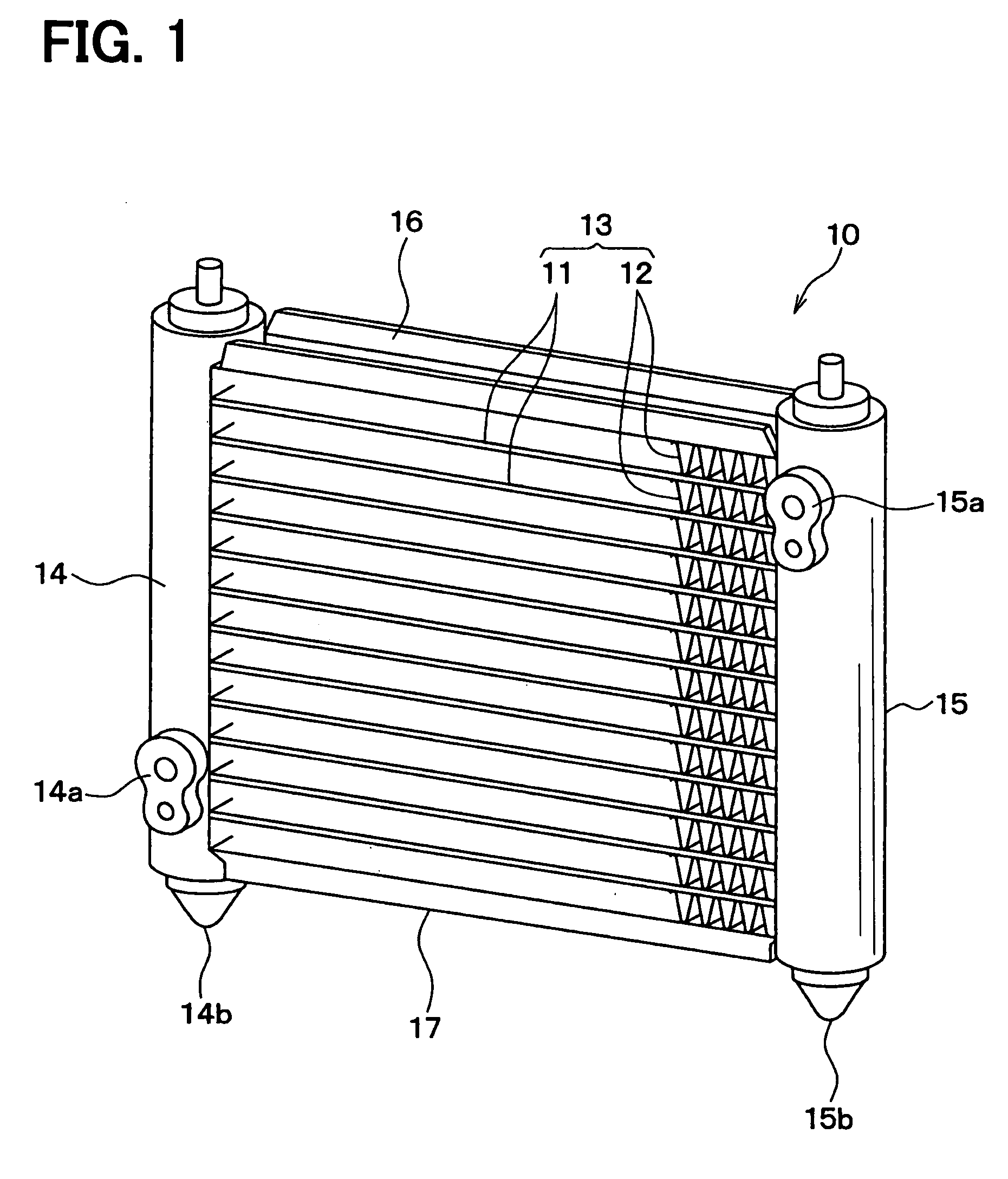
[0029]A first embodiment will be described with reference to FIGS. 1 to 7. As shown in FIG. 1, a heat exchanger 10 is for example used as a refrigerant condenser of a refrigerating cycle for a vehicle air conditioner, and is mounted in an engine compartment of a vehicle at a position where outside air is sufficiently supplied when the vehicle is running.
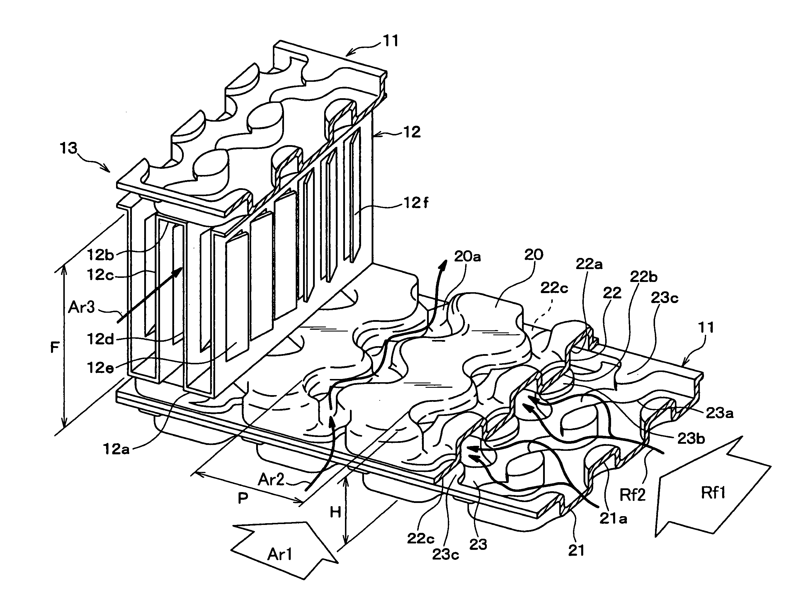
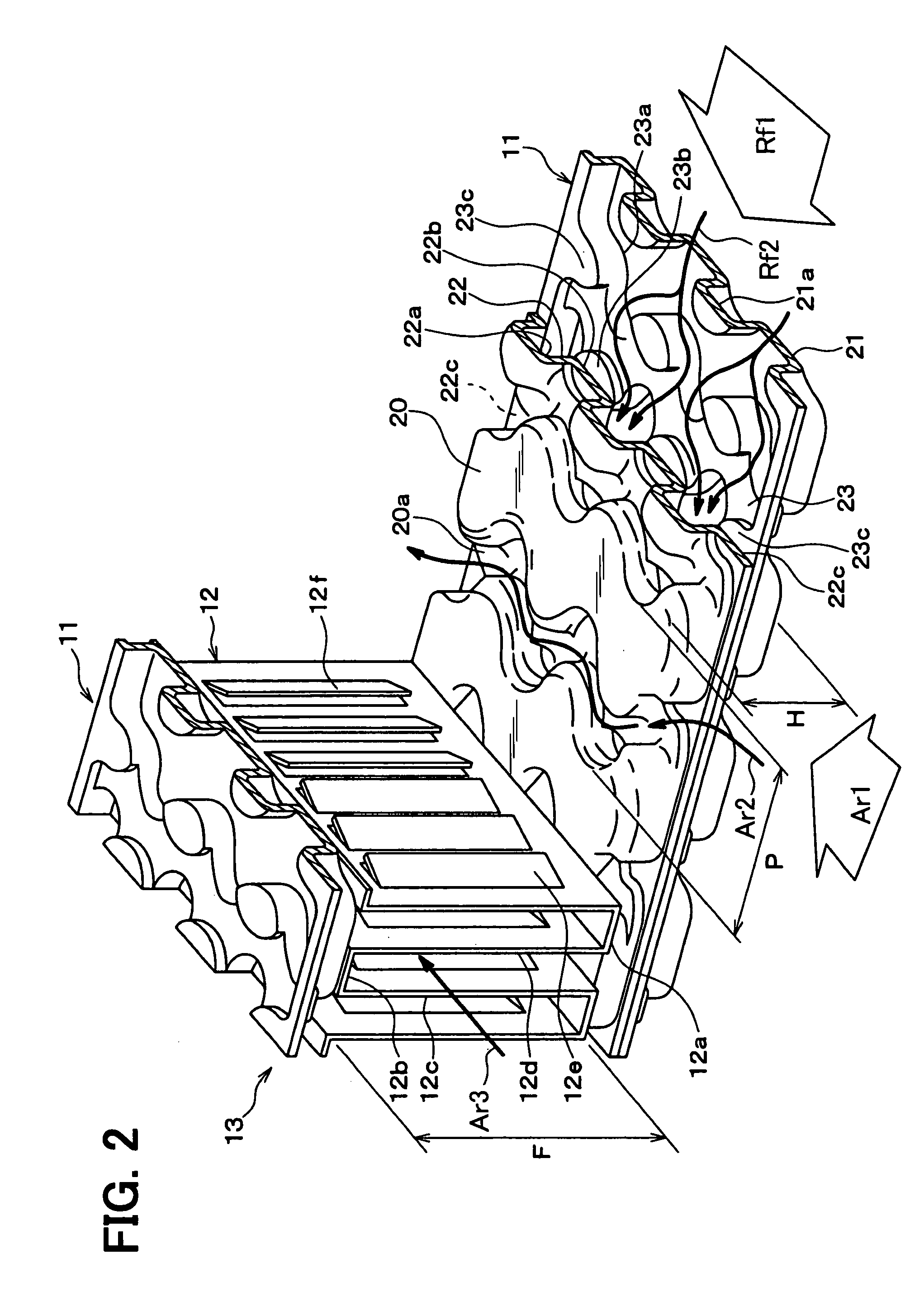
[0030]The heat exchanger 10 has a generally rectangular outline and includes a heat exchanging part 13 and tanks 14, 15. The heat exchanging part 13 includes flat tubes and fins 12. The flat tubes 11 define refrigerant passages therein through which a refrigerant flows. The fins 12 are for example corrugated fins. The heat exchanging part 13 performs heat exchange between the refrigerant and air flowing outside of the flat tubes 11.
[0031]The tanks 14, 15 are coupled to opposite longitudinal ends of the tubes 11. The refrigerant is distributed into the flat tubes 11 from one of the tanks 14, 15 (e.g., a left tank in FIG. 1) and is col...
second embodiment
[0087]A second embodiment will be described with reference to FIG. 8. As shown in FIG. 8, the fins 12 do not have the louvers 12e, 12f on the flat walls 12c, 12d. Structures of the heat exchanger 10 other than the louvers 12e, 12f are similar to those of the heat exchanger 10 of the first embodiment.
[0088]In the heat exchanger 10 of the second embodiment, because the efficiency of heat radiation of the fins 12 slightly reduces due to elimination of the louvers 12e, 12f, the efficiency Q slightly reduces as compared with the efficiency Q of the first embodiment. However, the tubes. 11 have the similar structure as the first embodiment. Therefore, effects substantially similar to the effects of the first embodiment are provided in the second embodiment.
[0089]Accordingly, the relationships between the efficiency Q and the tube height H, projection pitch P and fin height F have the similar trends as those of the first embodiment, though the efficiency Q is slightly reduced in this embod...
third embodiment
[0090]A third embodiment will be described with reference to FIG. 9. In the third embodiment, the heat exchanger 10 has the similar structure as that of the second embodiment other than corners 22a, 23a of the projections 22, 23.
[0091]In the second embodiment, the corners 22a, 23a are chamfered into the arc shape. In the third embodiment, on the other hand, the corners 22a, 23a are not chamfered. Instead, the side walls of the projections 22, 23 and the outer surfaces of the tube main walls 20, 21 form edged corners, as shown in FIG. 9.
[0092]Also in this case, the effects similar to the second embodiment are provided. Therefore, the relationships between the efficiency Q and the tube height H, projection pitch P and fin height F have the similar trends as those of the second embodiment.
PUM
 Abstract
Description
Claims
Application Information