

Lubrication Device
- Summary
- Abstract
- Description
- Claims
- Application Information
AI Technical Summary
Benefits of technology
Problems solved by technology
Method used
Image

Examples
Embodiment Construction
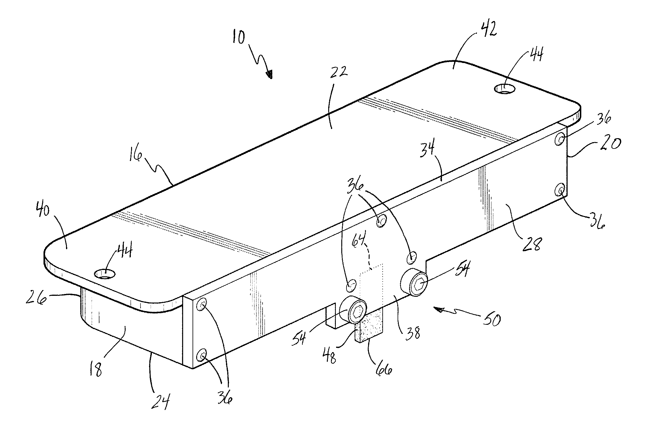
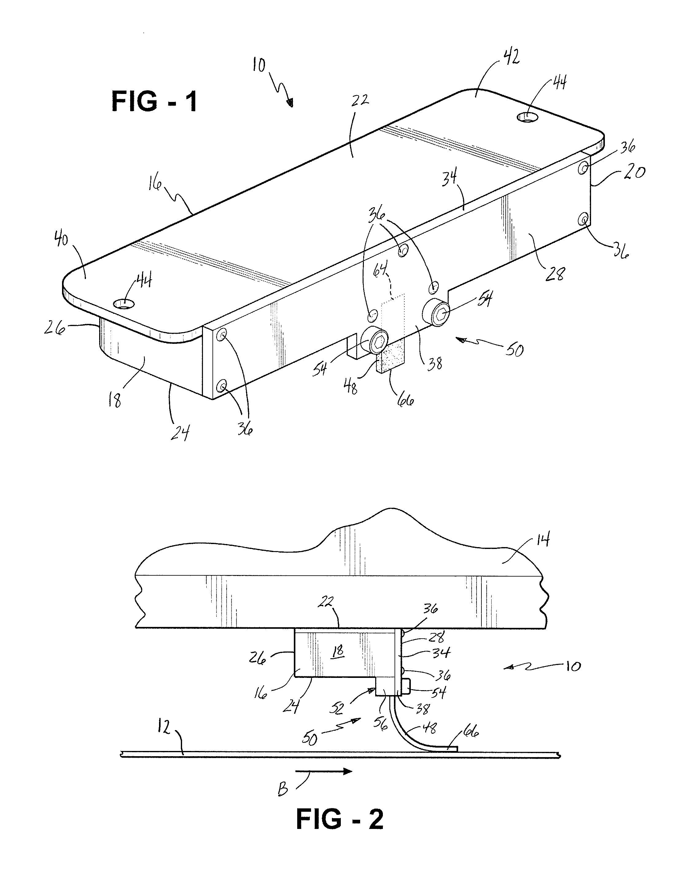
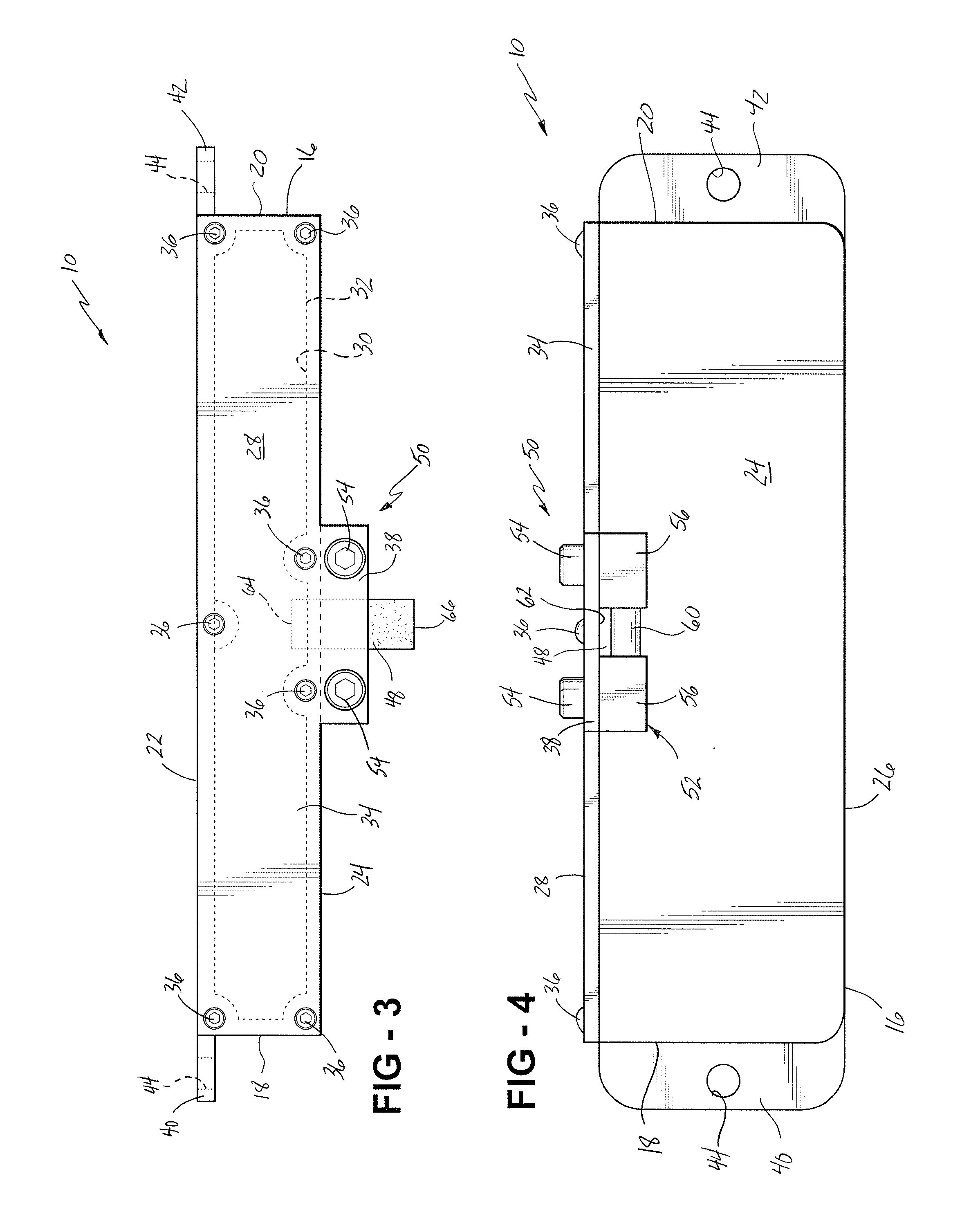
[0028] Referring to FIGS. 1 through 5, a lubrication assembly is generally shown at 10. In the embodiment shown, the lubrication assembly 10 is provided for lubricating a movable member or surface 12 and is adapted for mounting to a stationary member or surface 14, as is described in more detail below. The lubrication assembly 10 includes an elongated rectangular tube 16 extending between a first end 18 and a second end 20. The tube 16 includes a top side 22, a bottom side 24, a back side 26, and a front side 28 defining a reservoir 3O within the tube 16. The front side 28 includes an opening 32 therein. A removable front cover 34 is adapted to be fixedly secured to the front side 28 of the tube 16 for covering the opening 32. The front cover 34 is fixedly secured to the tube 16 using a plurality of screws 36 or other similar fasteners. The front cover 34 includes an integral clamping portion 38, the purpose of which is described below. It is appreciated that the tube 16 is not limi...
PUM
 Abstract
Description
Claims
Application Information