Deformable strainer

a strainer and strainer technology, applied in the field of food preparation implements, can solve the problems of user dropping the cooking vessel or its contents, hot steam typically rising from the cooking vessel, affecting the quality of food, etc., and reducing the risk of injuries to the user, preventing involuntary removal of food, and increasing the frictional force

Inactive Publication Date: 2007-10-04
SIMARD JO ANNE
View PDF9 Cites 10 Cited by
  • Summary
  • Abstract
  • Description
  • Claims
  • Application Information

AI Technical Summary

Benefits of technology

[0019] In accordance with the present invention, there is also provided, in combination, a cooking vessel and a strainer for straining liquids being poured through a pouring aperture of the cooking vessel, the cooking vessel having a vessel base wall and a vessel peripheral wall extending from the vessel base wall, the vessel peripheral wall defining a peripheral wall upper edge substantially circumventing the pouring aperture and a peripheral wall outer surface, the cooking vessel having a circumferential bead extending from the peripheral wall outer surface substantially adjacent the peripheral wall upper edge; the strainer being releasably attachable to the peripheral wall outer surface; the strainer comprising: a straining plate extending substantially through a plate geometrical plane, the straining plate having a plate first surface, an opposed plate second surface and a plate peripheral edge; the straining plate having straining apertures extending therethrough; an attachment flange extending substantially from the plate peripheral edge, the attachment flange having a flange contacting surface for frictionally contacting a circumferential contacting portion of the vessel peripheral wall so as to generate a frictional force between the flange contacting surface and the contacting portion of the vessel peripheral wall; the flange contacting surface being provided with a circumferential contacting surface groove, the contacting surface groove receiving the circumferential bead; at least a stretchable portion of the straining plate being made out of a resiliently deformable plate material so as to allow the straining plate to be stretchable substantially in the plate geometrical plane from a plate unstretched configuration wherein the plate peripheral edge has a peripheral edge first dimension to a plate stretched configuration wherein the plate peripheral edge has a peripheral edge second dimension, the peripheral edge second dimension being greater than the peripheral edge first dimension; wherein upon the straining plate being stretched towards the plate stretched configuration, the resilient nature of the stretchable portion of the straining plate biases the straining plate towards the plate unstretched configuration for exerting a compressive force on the contacting portion of the vessel peripheral wall and increasing the intensity of the frictional force between the flange contacting surface and the contacting portion of the vessel peripheral wall.
[0020] Advantages of the present invention include that the proposed cooking strainer is releasably mountable over the pouring aperture formed by conventional cooking vessels. The straining operation using the present invention hence only requires tipping of the cooking vessel with the proposed strainer mounted thereon without requiring the separate manipulation of a separate straining entity. The risk of injuries to the user and of creating a mess and / or wasting food is hence reduced.
[0021] The proposed cooking strainer is designed so as to be releasably secured over the pouring aperture of cooking containers in such a manner as to prevent involuntary removal thereof while the liquids are being poured from the cooking vessel and the solids retained therein.
[0022] The proposed cooking strainer is designed so as to be readily adaptable or adjustable to cooking vessels of various sizes. Furthermore, the proposed cooking strainer is designed so as to be substantially ergonomically attachable and detachable to and from a conventional cooking vessel without requiring manual dexterity or excessive strength.
[0023] Furthermore, the proposed cooking strainer is designed so as to be manufacturable using conventional forms of manufacturing and conventional materials through a relatively simple manufacturing process such as injection moulding so as to provide a cooking strainer that will be economically feasible, long-lasting and relatively trouble-free in operation.

Problems solved by technology

This tilting action is often considered unergonomical and can cause the user to drop the cooking vessel or its contents, especially as the weight of the cooking vessel shifts.
Also, if the cook transfers the food and liquid too quickly, the liquid may splash onto the cook's face or body, or onto the surrounding countertop and / or floor.
In addition, the food itself may not fall directly from the cooking vessel into the strainer and may land in the sink, on the floor, or other undesired locations.
Furthermore, if the food has been boiled, hot steam typically rises from the cooking vessel.
Hence, if boiling liquid is poured out of the cooking vessel, the cook's arms and hands may be exposed to the steam, potentially resulting in a burn injury.
Another problem associated with conventional strainers is the fact that such conventional strainers are not adapted to be used with various sizes of cooking vessels.
When there is not a good fit between the strainer and the cooking vessel, the hereinabove-mentioned problems are compounded.

Method used


Image

  • Deformable strainer
  • Deformable strainer
  • Deformable strainer

Examples


Embodiment Construction

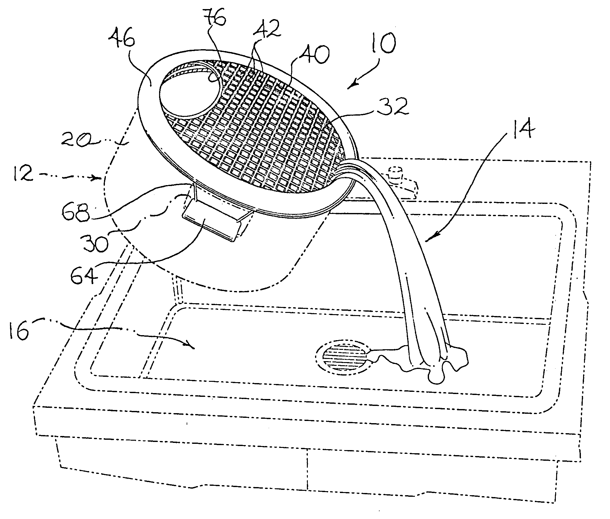
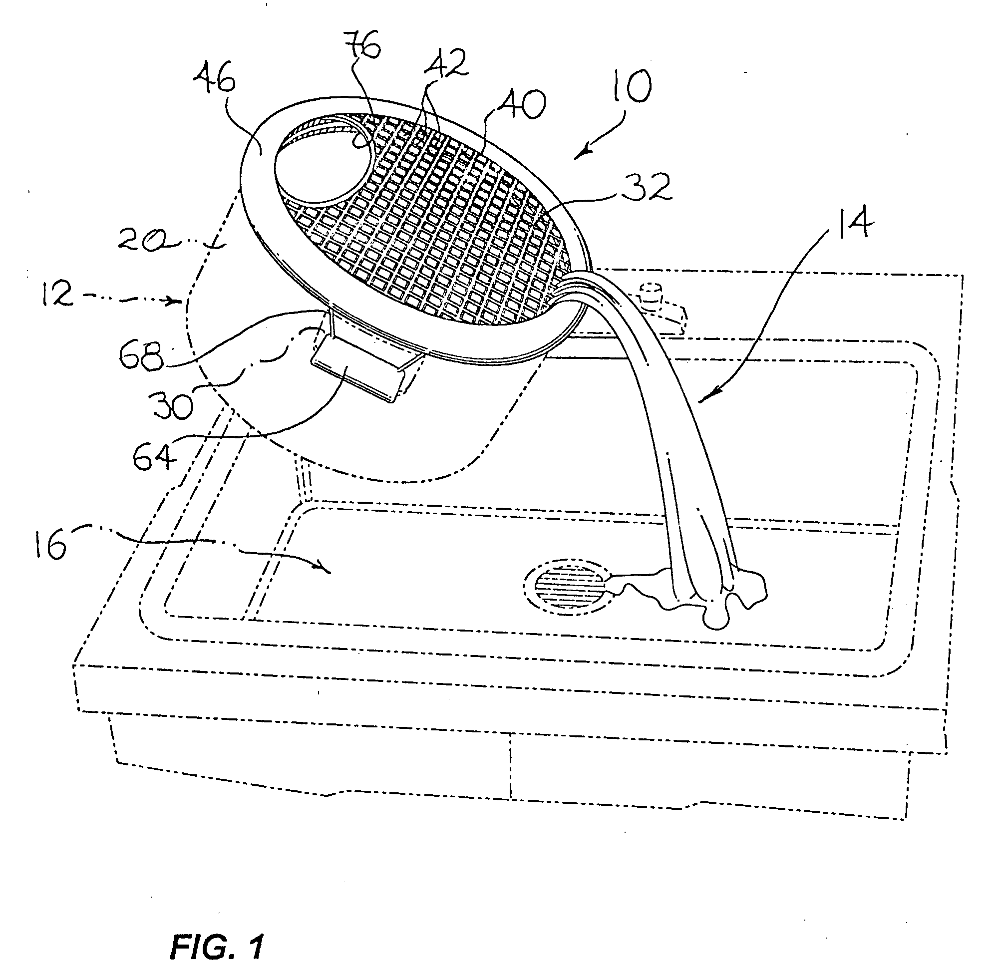
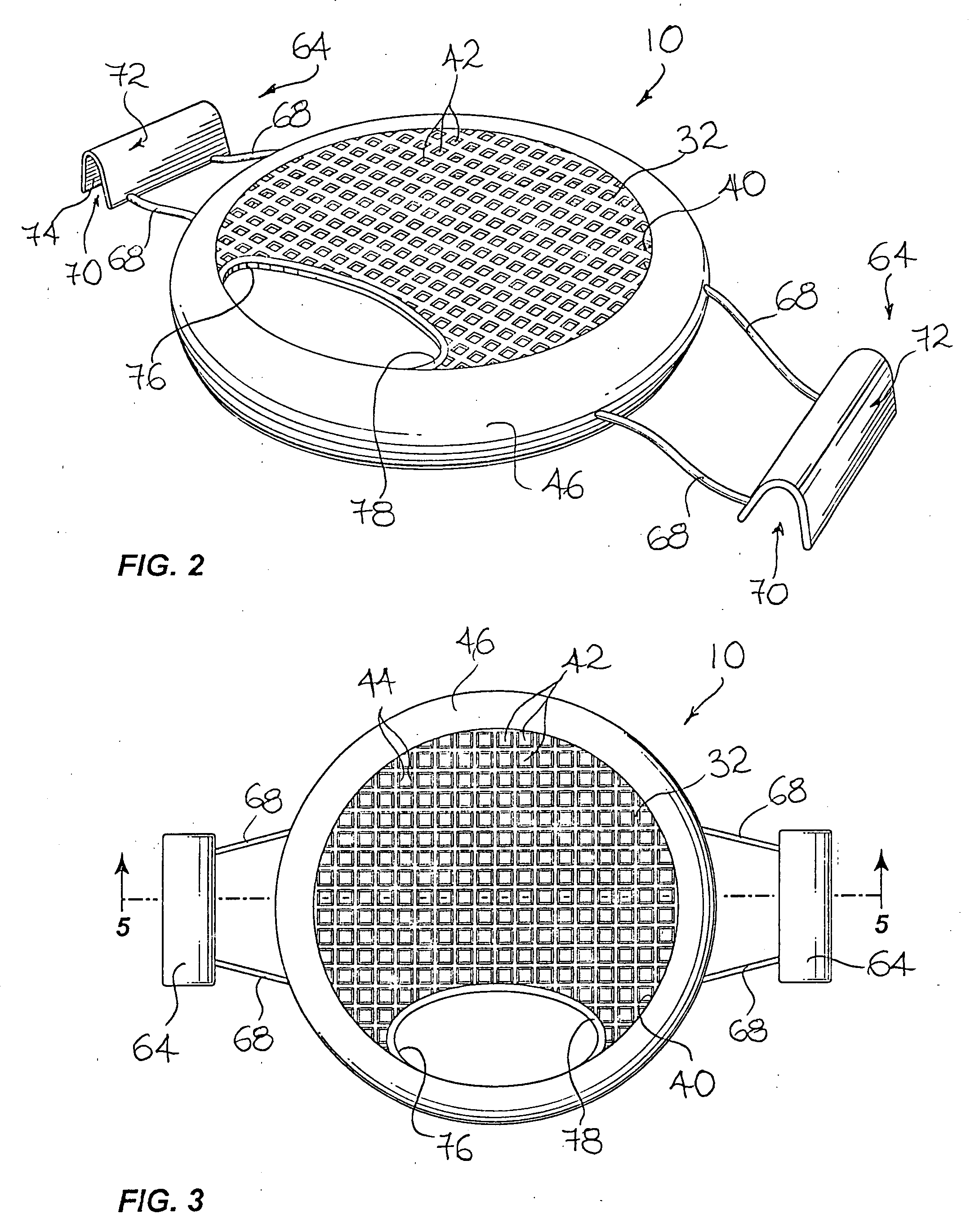
[0038] Referring to FIG. 1, there is shown a strainer in accordance with an embodiment of the present invention, generally indicated by the reference numeral 10. The strainer 10 is shown mounted on a conventional cooking vessel generally indicated by the reference numeral 12. It should be understood that although FIG. 1 illustrates the strainer 10 mounted, by way of example, on a conventional boiling pot-type cooking vessel, the strainer 10 could be used on any other suitable type of vessels including any other suitable cooking vessels such as pots, pans, or the like of various sizes and configurations without departing from the scope of the present invention.

[0039] In FIG. 1, the strainer 10 is shown straining a liquid from a solid. The liquid, generally indicated by the reference numeral 14, is shown being poured out of the cooking vessel 12 through the strainer 10 into a sink, generally indicated by the reference numeral 16. It should, however, be understood that the strainer 10...


PUM

PropertyMeasurementUnit
frictional forceaaaaaaaaaa
stretchableaaaaaaaaaa
compressive forceaaaaaaaaaa

Abstract

A strainer mountable over the pouring aperture of a cooking vessel includes a straining plate having straining apertures extending therethrough. An attachment flange extends from the plate peripheral edge and defines a flange contacting surface for frictionally contacting the peripheral wall of the vessel so as to generate a frictional force therebetween. The straining plate is made out of a resiliently deformable material so as to allow the straining plate to be stretchable from an unstretched configuration to a stretched configuration. Upon the straining plate being stretched towards the plate stretched configuration, the resilient nature of the straining plate biases the straining plate towards the plate unstretched configuration for exerting a compressive force on the peripheral wall of the vessel and increasing the intensity of the frictional force.

Description

FIELD OF THE INVENTION [0001] The present invention relates to the general field of food preparation implements and is particularly concerned with a deformable strainer. BACKGROUND OF THE INVENTION [0002] There exists a plurality of situations wherein, in the preparation of food, it is desirable to separate or strain a liquid from a solid. For example, it is often desirable to drain cooking liquids such as water out of a cooking vessel in which a given food such as vegetables, pasta or the like has boiled or otherwise been cooked. [0003] The conventional straining operation is typically performed using conventional strainers. These conventional strainers typically are substantially bowl or pot-shaped and may incorporate one or more features such as a single handle, a pair of handles or an extended handle and leg combination. These conventional strainers typically include drainage apertures that vary in number and size in proportion to the items to be strained. The volume of these co...

Claims


Application Information

Patent Timeline
Patent Type & Authority Applications(United States)
IPC IPC(8): B01D35/02
CPCA47J36/08A47J43/284A47J36/14
Inventor SIMARD, JO-ANNE
Owner SIMARD JO ANNE
Why Eureka
Try Eureka