Imaging-based bar code reader with rotated photosensor array

a photosensor array and bar code reader technology, applied in the field of image-based bar code readers, can solve the problems of increasing the cost of imaging system, not readily applicable to hand-held bar code readers, etc., and achieve the effect of convenient us

Inactive Publication Date: 2007-10-04
SYMBOL TECH INC
View PDF4 Cites 25 Cited by
  • Summary
  • Abstract
  • Description
  • Claims
  • Application Information

AI Technical Summary

Benefits of technology

[0010] In one preferred embodiment of the present invention, the reader housing is capable of both being used in a fixed position and in a hand-held mode. The housing includes a gripping portion adapted to be grasped by an operator and a forward portion extending from the gripping portion, the forward portion supporting the window. The bottom portion of the gripping portion is adapted to be received and supported in a docking station supported on a substrate such as a tabletop or sales counter. To facilitate using the reader in the hand-held mode, a leading or upper edge of the forward portion housing may be configured to be substantially parallel with the horizontal axis of the housing window to aid in alignment of the housing window with a target bar code since, in the hand-held mode, the operator is holding the gripping portion of the housing and pointing or aiming the forward portion of the housing toward the target code and, therefore, does not see the housing window but instead aligns the upper edge of the housing with the horizontal axis of the target bar code.

Problems solved by technology

However, increasing pixel count increases imaging system cost.
While this approach is useful, it is not readily applicable to hand-held bar code readers where the operator would have to move the bar code reader at an angle with respect to a horizontal axis of a bar code being read which is counterintuitive.

Method used


Image

  • Imaging-based bar code reader with rotated photosensor array
  • Imaging-based bar code reader with rotated photosensor array
  • Imaging-based bar code reader with rotated photosensor array

Examples


Embodiment Construction

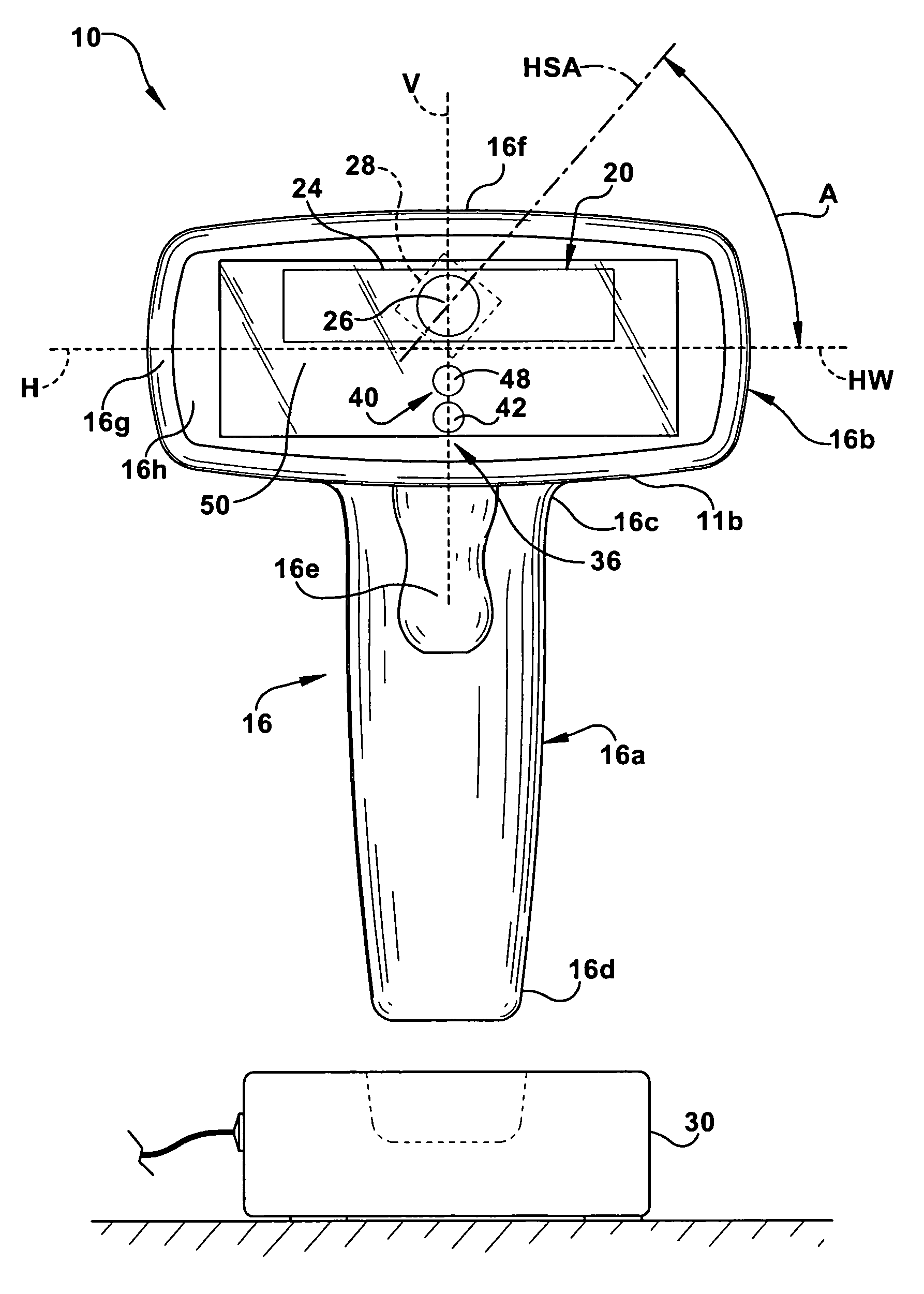
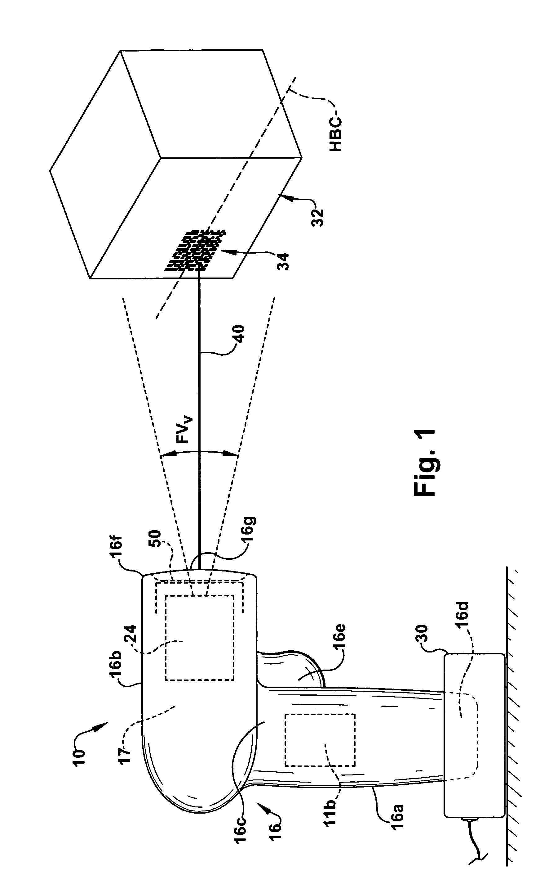
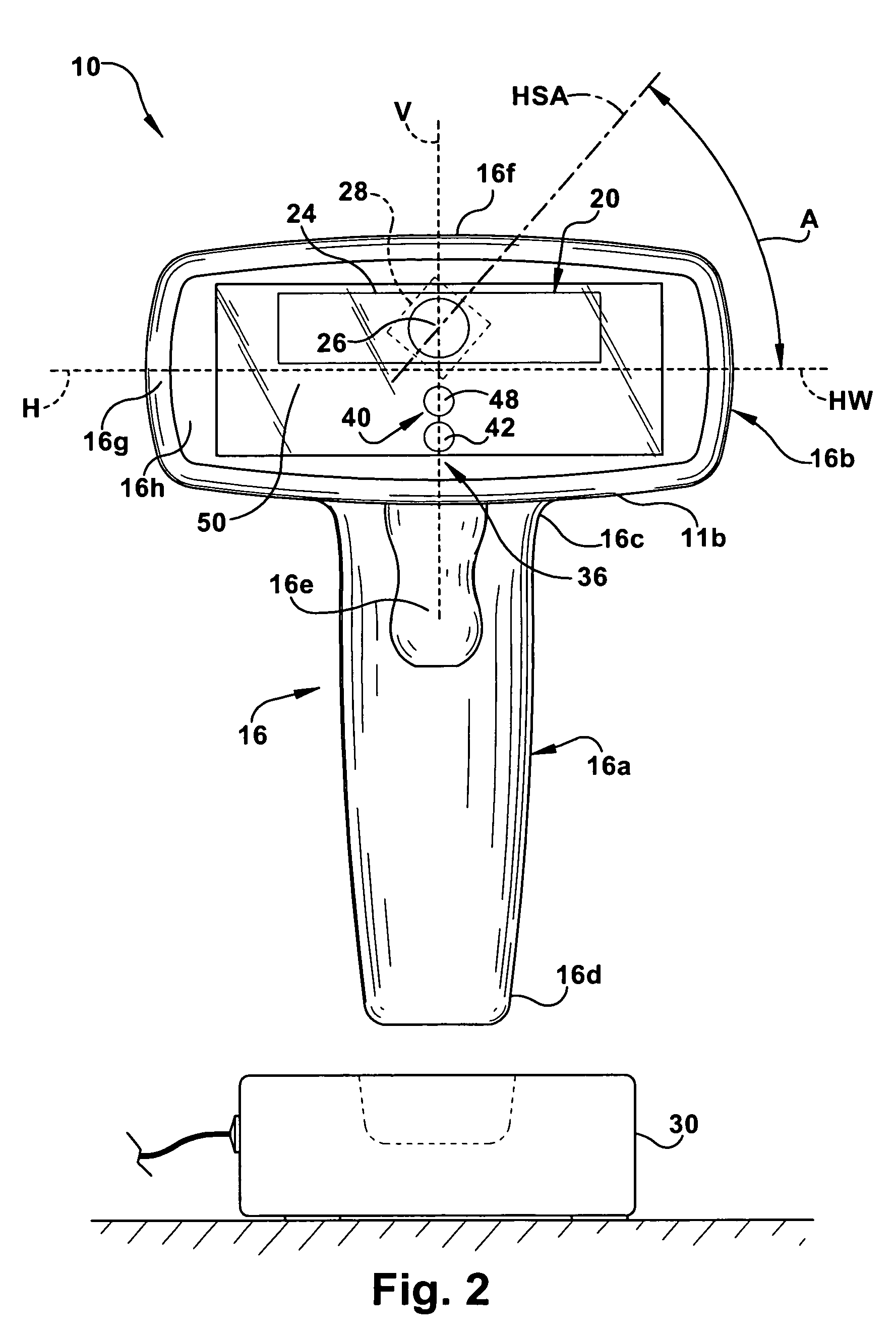
[0022] An exemplary embodiment of an imaging-based bar code reader is shown schematically at 10 in FIGS. 1-5. The bar code reader 10 includes a two dimensional (2D) imaging system 12 and a decoding system 14 mounted in a housing 16 and is capable of reading, that is, imaging and decoding both 1D and 2D bar codes and postal codes. The reader 10 is also capable of capturing images and signatures. The imaging system 12 is adapted to capture image frames of a field of view FV of the imaging system 20 and the decoding system 14 is adapted to decode encoded indicia within a captured image frame. The housing 14 supports circuitry 11 of the reader 10 including the imaging and decoding systems 12, 14 within an interior region 17 of the housing 16.

[0023] The imaging system 12 comprises an imaging camera assembly 20 and associated imaging circuitry 22. The imaging camera 20 includes a housing 24 supporting focusing optics including a focusing lens 26 and a 2D sensor or pixel array 28. The sen...


PUM


Abstract

An imaging based bar code reader for imaging and decoding a target bar code. The reader features a housing including a scanning head defining a horizontal axis and an imaging system supported by the housing for imaging the target bar code. The imaging system including a 2D sensor array and focusing optics receiving reflected illumination from the target bar code through the window and focusing the reflected illumination onto the sensor array. The sensor array includes an orthogonal array of pixels and defines a horizontal axis. The reader further features a decoding system for decoding an image of the target bar code. The sensor array is oriented such that the horizontal axis of the sensor array is at an acute angle with respect to the horizontal axis of the target bar code when the target bar code is being presented to the scanning head such that the horizontal axis of the target bar code is substantially parallel to the horizontal axis of the scanning head.

Description

FIELD OF THE INVENTION [0001] The present invention relates to an imaging-based bar code reader including a sensor array which is rotated about an axis perpendicular to a sensor array surface such that a horizontal axis of the sensor array surface is at an acute angle with respect to a horizontal axis of a target bar code when the target bar code is presented for reading. BACKGROUND OF THE INVENTION [0002] Various electro-optical systems have been developed for reading optical indicia, such as bar codes. A bar code is a coded pattern of graphical indicia comprised of a series of bars and spaces of varying widths, the bars and spaces having differing light reflecting characteristics. Systems that read and decode bar codes employing CCD or CMOS-based imaging systems are typically referred to as imaging-based bar code readers or bar code scanners. [0003] The bar code reader includes an imaging and decoding system including an imaging system for generating an image of a target bar code ...

Claims


Application Information

Patent Timeline
Patent Type & Authority Applications(United States)
IPC IPC(8): G06K7/10
CPCG06K7/10851G06K7/10722
Inventor VINOGRADOV, IGOR R.CARLSON, BRADLEY S.BARKAN, EDWARD
Owner SYMBOL TECH INC
Why Eureka
Try Eureka