Rope Winding System for Winding and Unwinding Steel Ropes of Cranes

a technology for winding systems and cranes, which is applied in the direction of magnets, hoisting equipments, magnetic bodies, etc., can solve the problems of high wear and tear of steel ropes, different load of rollers, and complex construction, and achieve the effect of facilitating uniform winding of steel ropes

Active Publication Date: 2007-10-04
TADANO DEMAG GMBH
View PDF6 Cites 32 Cited by
  • Summary
  • Abstract
  • Description
  • Claims
  • Application Information

AI Technical Summary

Benefits of technology

[0011] According to a first aspect of the present invention, a rope winding system is provided which reliably facilitates uniform winding of a steel rope onto a rope drum. A rope winding system of the present invention for winding and unwinding a steel rope of a crane comprises a rope drum, onto which the steel rope is to be wound in several layers, and a magnetic system which is arranged in such a way that a magnetic field can be generated with its magnetic flux being deflected by a movement of the steel rope in such a way that the steel rope is braided.
[0012] The invention is based on the idea that at least a section of the steel rope is exposed to a magnetic field, which is in particular stationary, in such a way that when the steel rope moves, i.e. for example during a rope winding operation, a direct rope load is exerted on the steel rope. By moving the steel rope through the magnetic field, a force component is generated which exerts a direct rope load on the rope and therefore brakes it, which results in an improved winding-up operation. The braking effect is generated by deflecting the rope in the magnetic field. In particular, there is no mechanical contact between the magnetic system of the rope winding system and the steel rope. The mechanical stress on the steel rope can therefore preferably be kept to a minimum and wear and tear is minimal. It has to be noted that the magnetic system can be arranged in the vicinity of the rope drum or in a distance therefrom. In an exemplary embodiment of the invention the magnetic system is arranged in front of the rope drum. Alternatively, a considerable distance between the rope drum and the magnetic system can be arranged and further components such as e.g. one or more deflection pulleys for deflecting the rope dropping out of the magnetic system can be arranged between the rope drum and the magnetic system. It can be sufficient that a braking force is exerted on the rope acting to ensure that tension is maintained on portion of the rope between the rope drum and the magnetic system. Hence, the implementation of the present invention is relatively easy and can be adapted to existing arrangement without problems.
[0015] In another exemplary embodiment of the present invention, the magnetic system has an eddy current brake. Since the brake does not touch the steel rope in order to exert a braking force, it is free of wear and tear and therefore provides for low-cost maintenance. The functioning of the eddy current brake is based on the law of induction. Eddy current brakes consist of an iron yoke with a plurality of pole cores. Electric windings excite the brake magnetically in such a way that alternating electric north and south poles occur. When the rope is moved through the excited eddy current brake, magnetic fields caused by the eddy currents are generated from which the braking force results. Since there is no contact between the brake and the rope, the wear and tear on the rope is minimized.
[0020] In another exemplary embodiment of the present invention, the sensor is mounted on the magnetic system. The magnetic system may be, for example, a means for adjusting the braking force exerted on the steel rope and therefore the rope load of the steel rope, so that the latter may be continuously detected and controlled, with or without feedback, making it possible for an optimal rope load to be applied whenever the steel rope is wound onto the rope drum.

Problems solved by technology

The pressure rollers used do not, however, always contact the entire width of the rope drum, so that the pressure roller experiences different loads as the rope is wound up.
The use of pressure rollers results in high wear and tear of the steel rope.
Also, pressure rollers tend to skip, which may lead to damage.
This construction is, however, very complex and only results in transferring the rope to the inner drum.
Difficulty has arisen in the past since there is almost inevitably appreciable slip.

Method used


Image

  • Rope Winding System for Winding and Unwinding Steel Ropes of Cranes
  • Rope Winding System for Winding and Unwinding Steel Ropes of Cranes
  • Rope Winding System for Winding and Unwinding Steel Ropes of Cranes

Examples


Embodiment Construction

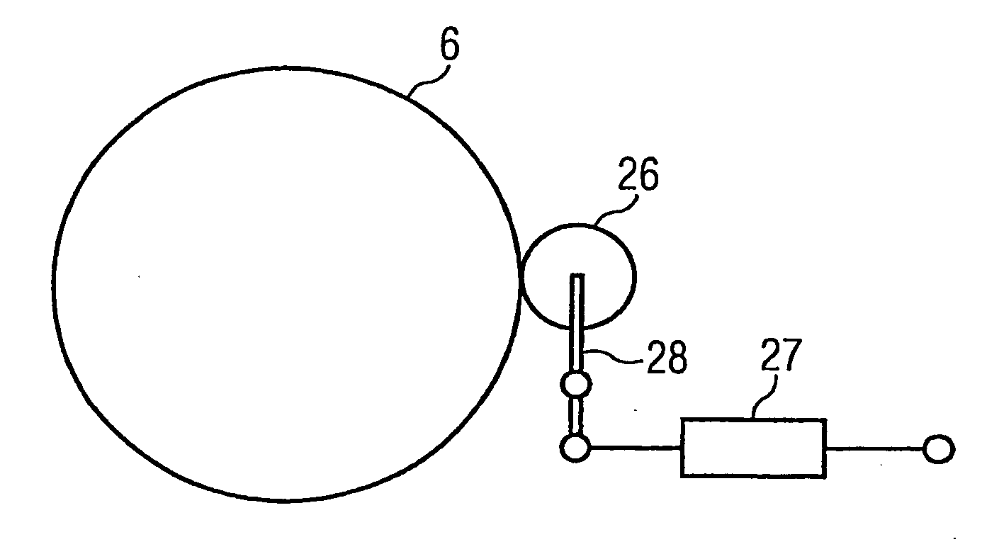
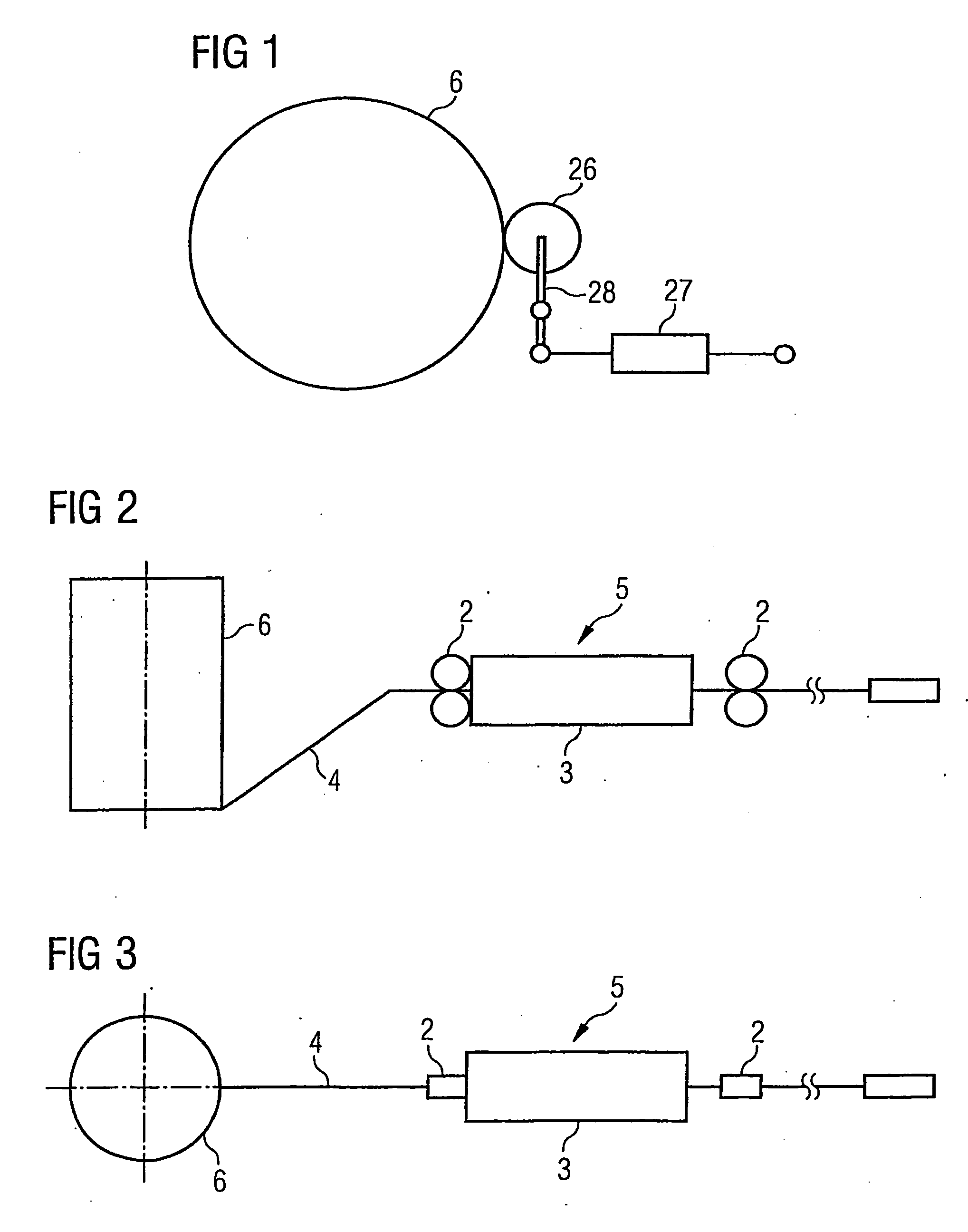
[0033]FIG. 1 shows a side view of an apparatus for winding up a steel rope onto a rope drum 6 of the conventional type, which uses a pressure roller 26 to generate a rope load. Pressure roller 26 is linked to a hydraulic cylinder 27 via a lever 28. Pressure roller 26 serves to lay the steel rope and should prohibit a lift-off the rope at slack rope problems.

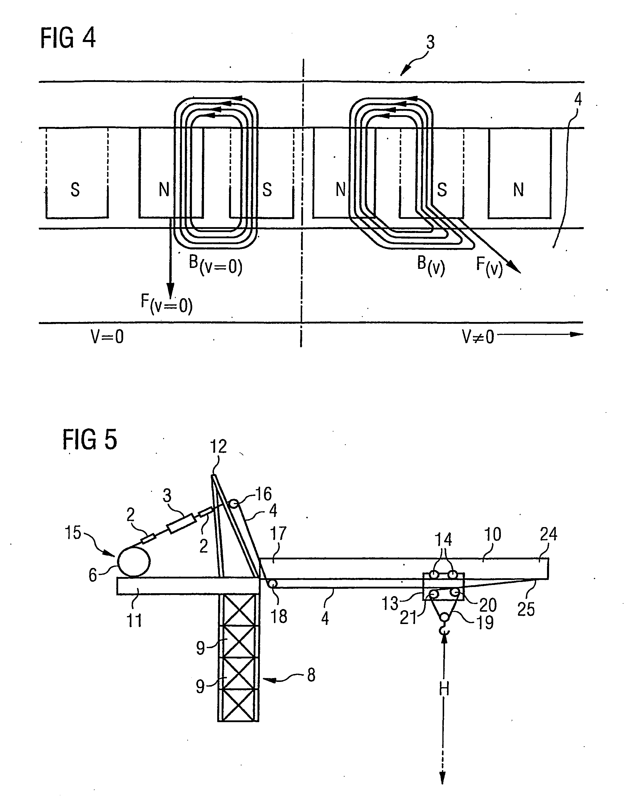
[0034]FIG. 2 shows, in a side view, a rope winding system 1 according to the present invention. To generate a rope load on steel rope 4, a magnetic system 3 in the form of an eddy current brake is used. When rope drum 6 winds up steel rope 4, an electric current is supplied to eddy current brake 3 and steel rope 4 is braked by the magnetic field which is deflected by the movement of steel rope 4 through the magnetic field. In front of eddy current brake 3, a pair of opposed guiding pulleys 2 is arranged, which guide steel rope 4 into the magnetic field of eddy current brake 3. After it has passed through eddy current brake 3, st...


PUM


Abstract

The present invention relates to a rope winding system (1) for winding and unwinding a steel rope (4) of a crane (7). A rope winding system (1) according to the present invention has a rope drum (6), onto which the steel rope (4) can be wound in a plurality of layers, and a magnetic system (7) which is configured to generate a magnetic field over a section of the steel rope (4) with its magnetic flux being deflected by a movement of the steel rope (4) in such a way that the steel rope (4) is braked. A crane (7) is also discloses which is equipped with such a rope winding system (1) for winding and unwinding a steel rope (4).

Description

CROSS-REFERENCE TO RELATED APPLICATIONS [0001] The present application claims the benefit under 35 U.S.C. § 371 of PCT Application No. PCT / EP2005 / 004661, filed Apr. 29, 2005 which is hereby incorporated by reference in its entirety. Further, the present application claims priority under 35 U.S.C. § 119 (e) of U.S. Provisional Patent Application No. 60 / 566,549 filed Apr. 29, 2004 which is incorporated by reference in its entirety.TECHNICAL FIELD OF THE INVENTION [0002] The present invention relates to rope winding systems for winding and unwinding steel ropes of a crane, and to a crane which is equipped with such a rope winding system. Cranes of the construction of interest comprise for example mobile cranes, in particular telescopic boom cranes, but also tower slewing cranes, in particular top and bottom slewing cranes. BACKGROUND OF THE INVENTION [0003] Generally rope winding systems are well known which use various techniques or constructions in order to apply a more or less const...

Claims


Application Information

Patent Timeline
Patent Type & Authority Applications(United States)
IPC IPC(8): B66D5/16B66D1/52
CPCB66D5/30B66D5/16
Inventor SCHARF, THORSTENNOESKE, INGO
Owner TADANO DEMAG GMBH
Why Eureka
Try Eureka