Gapped motor with outer rotor and stationary shaft

Inactive Publication Date: 2007-10-04
PRECISION MAGNETIC BEARING SYST
View PDF24 Cites 20 Cited by
  • Summary
  • Abstract
  • Description
  • Claims
  • Application Information

AI Technical Summary

Benefits of technology

[0009] The invention discloses a novel stator winding and core configuration with no slots. The invention relates to permanent magnet motors. Of special interest are those with rotors enclosing an internal stator. Such motors are used in wide ranging ap

Problems solved by technology

Few commercial motors are of the axial gap type, that employ flat disc shaped rotors and toroidal cores separated by an axial gap.
Conductors outside the segments, called end windings, do not produce torque, but do

Method used


Image

  • Gapped motor with outer rotor and stationary shaft
  • Gapped motor with outer rotor and stationary shaft
  • Gapped motor with outer rotor and stationary shaft

Examples


Embodiment Construction

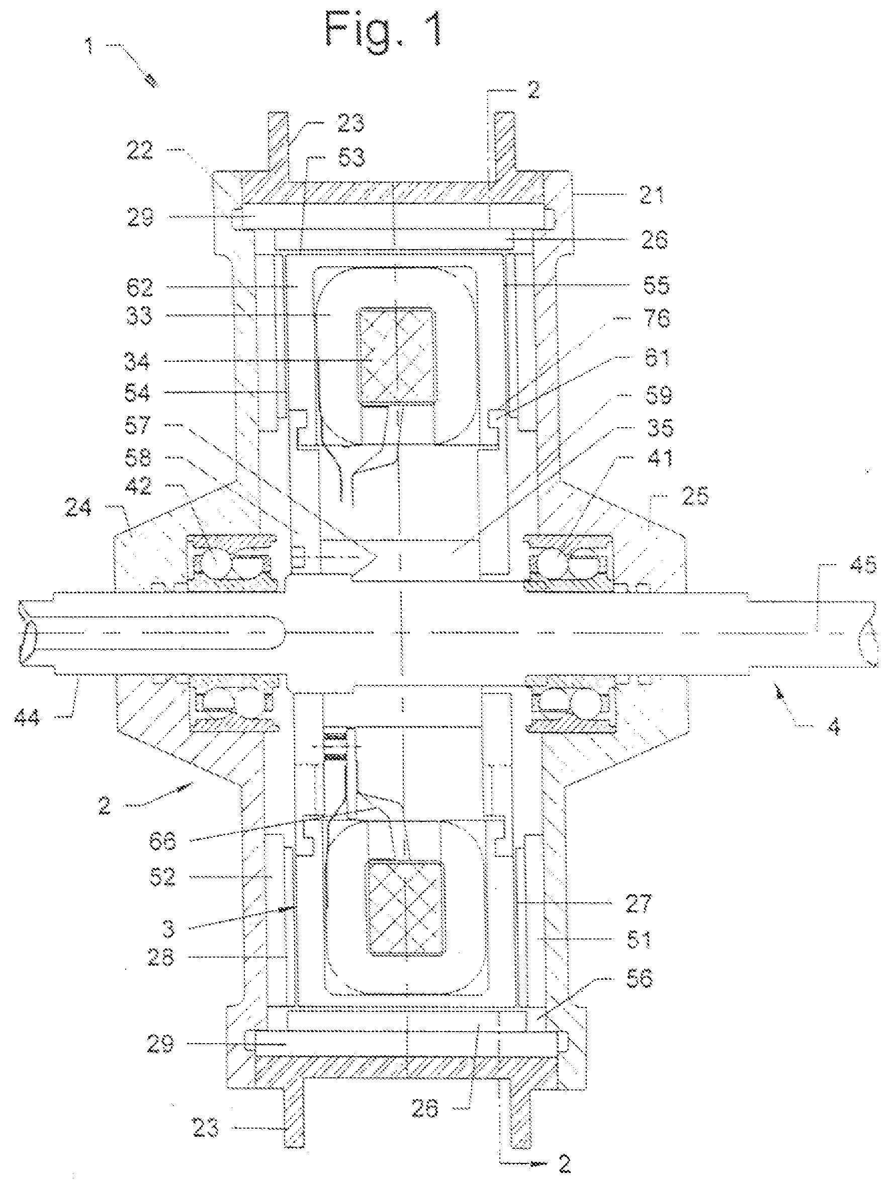
[0020]FIG. 1 shows a front cross-sectional view of the three-gapped motor. The motor 1 consists of a rotor subassembly 2, a stator subassembly 3 and a shaft subassembly 4. The rotor support structure consists of two disc-shaped rotor brackets 21, 22 sandwiching a rotor shell 23. The rotor brackets 21, 22 have hub portions 24, 25 at their center or inner ends; a non-rotating shaft 44 extends through the openings of the hubs 24, 25 and are connected to the rotor subassembly 2 by two ball bearings 41, 42 as shown. The bearings may be of angular contact or roller bearings type depending on the size and application requirements. The rotor subassembly 2 rotates over the stationary shaft 44 on the bearings 41, 42.

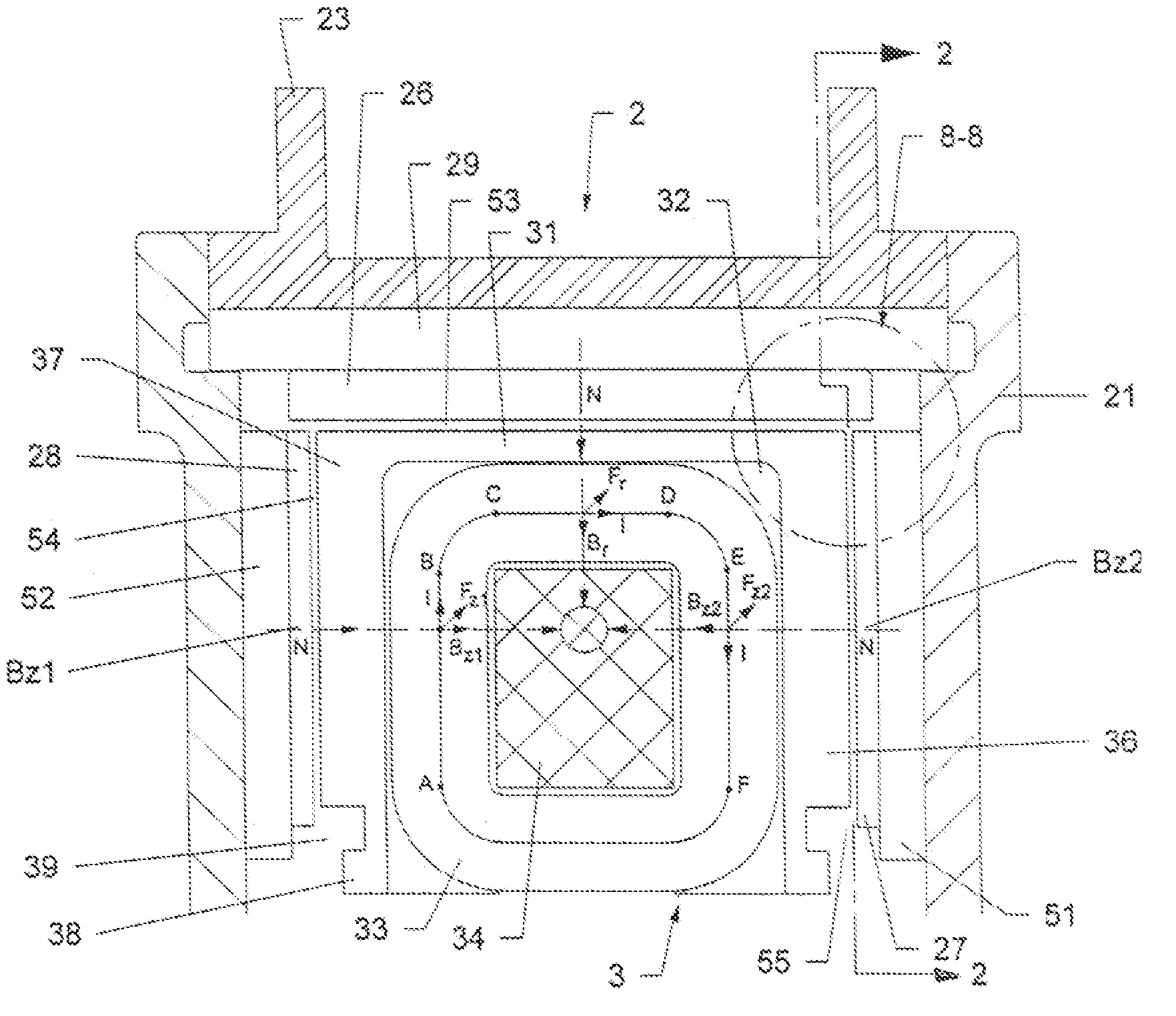
[0021] With reference to FIGS. 1 and 2, FIG. 2 is an end or side view along the section lines 2-2 in FIG. 1 (and FIG. 7) showing the magnet arrangement and support of the rotor 2. Three sets of permanent magnets are fastened to the rotor support structure, one radial 26 and two a...


PUM


Abstract

A gapped motor produces higher torque than existing one or two gap motors. The motor uses both one radial and one axial gap or two axial gaps to produce torque. A single stator is provided with an essentially U-shaped rotor shell having permanent magnets with back iron. The stator has loops of coil windings separated by pole pieces. Current flowing in segments of the coils interacts with the fields from the permanent magnets to produce more torque. The plane of the coils extends through the centerline of the stator. In a given plane through the motor axis, the same polarity of the magnets on the rotor face the stator.

Description

BACKGROUND OF THE INVENTION [0001] 1. Field of the Invention [0002] A gapped motor has a “U” shape rotor, with permanent magnets on the radial inner surfaces and axial surfaces, that rotate over coils positioned radially on a stator. [0003] 2. Description of Related Art [0004] At present most commercial motors have radial gaps separating the rotor and stator. Those with permanent magnets have cylindrical rotors attached to a rotating shaft covered by stationary lamination stacks, with the rotor and stator separated by a radial gap. Arc shaped permanent magnets are mounted around the outer periphery of the rotor and face radially outward. Several pairs of magnets of alternating polarity are disposed around the rotor producing rotating magnetic fields within the radial air gap. Stator windings are placed in slots within the stationary lamination stack and loop from one slot to another. Conductor segments within the slots link gap fields to produce torque. Coil segments that are outsid...

Claims


Application Information

Patent Timeline
IPC IPC(8): H02K19/00H02K1/00H02K1/12H02K21/12
CPCH02K1/12H02K21/24H02K21/22H02K21/12
Inventor RAO, DANTAM K.
Owner PRECISION MAGNETIC BEARING SYST
Why Eureka
Try Eureka