Interior permanent magnet rotors with multiple properties and methods of making same

a technology of internal permanent magnets and rotors, which is applied in the direction of rotating magnets, dynamo-electric components, synchronous machines, etc., can solve the problems of low energy magnetic, torque ripple and loss, and reduce the average torque production

Inactive Publication Date: 2007-10-04
GM GLOBAL TECH OPERATIONS LLC
View PDF10 Cites 58 Cited by
  • Summary
  • Abstract
  • Description
  • Claims
  • Application Information

AI Technical Summary

Problems solved by technology

However, in this patent high energy magnetic material in the middle section or the inner regions of the rotor are not exposed to a magnetizing field strong enough to fully magnetize high energy magnetic material.
Consequently, low energy magnetic material is placed in areas of the rotor that are difficult to magnetize because low energy magnetic materials require a smaller magnitude magnetizing field than high energy magne

Method used


Image

  • Interior permanent magnet rotors with multiple properties and methods of making same
  • Interior permanent magnet rotors with multiple properties and methods of making same
  • Interior permanent magnet rotors with multiple properties and methods of making same

Examples


Embodiment Construction

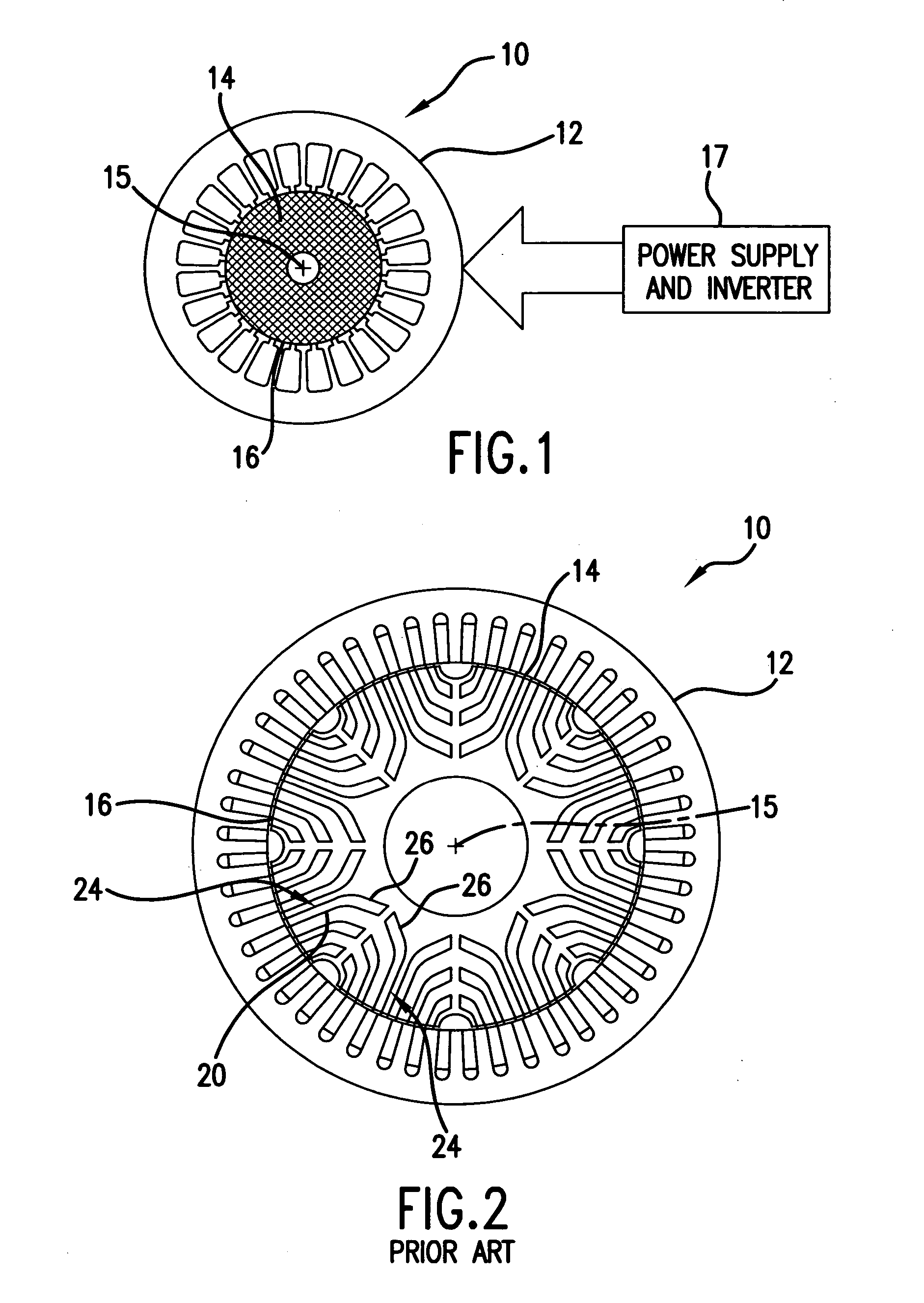
[0019]FIG. 1 is a diagrammatic drawing of a permanent magnet motor 10 having a wound stator 12 and a permanent magnet rotor 14. The rotor 14 is formed around a longitudinal axis 15 and a peripheral surface 16. A power supply and inverter 17 communicate and control the speed and torque of the motor 10 in response to feedback including, but not limited to, an encoder, resolver, tachometer, proximity switch and tooth set, and back electromotive force (emf) detection. The motor 10 may be characterized as a brushless DC motor with square wave or sinewave excitation provided by the power supply and inverter 17.

[0020]FIG. 2 is a cross-section of a prior art multi-layer or barrier buried magnet rotor geometry. Permanent magnets 20 are defined by regions 26 of magnetic material layers or barriers 24 that are difficult to fully magnetize because of a relatively long distance from the peripheral surface 16 of the rotor 14. The surface of the magnetic material layers 24 are magnetized by a mag...


PUM

PropertyMeasurementUnit
Strengthaaaaaaaaaa
Distanceaaaaaaaaaa
Energyaaaaaaaaaa

Abstract

An armature for use in an electric traction motor comprises a rotor having a central portion and a peripheral portion with the peripheral portion having a plurality of cavities. Permanent magnets solidified from liquid magnetic material are disposed in the cavities to form poles of the rotor with at least a portion of the cavities having directly abutting permanent magnets comprised of at least first and second magnetic materials of different properties injected in liquid or mobile form into single cavities. In interface regions between the at least first and second magnetic materials the first and second magnetic materials are intermingled to form a transition zone. A method of making the armature includes injecting the magnetic materials simultaneously as well as injecting a subsequent magnetic material when the initial magnetic material is still fluidly mobile.

Description

FIELD OF THE INVENTION [0001] The present invention relates to interior permanent magnet rotors with multiple properties and methods for making same. More particularly, the present invention relates to such rotors configured for use in electric motors used in electric or hybrid vehicles, or in electric motors used for other purposes. BACKGROUND OF THE INVENTION [0002] The type and strength of magnetic material in different regions of a rotor used in electric motors may be varied. For example in U.S. Pat. No. 6,703,746, NdFeB is used to configure in the entire outer barrier of the rotor where it may be easily magnetized. However, in this patent high energy magnetic material in the middle section or the inner regions of the rotor are not exposed to a magnetizing field strong enough to fully magnetize high energy magnetic material. Consequently, low energy magnetic material is placed in areas of the rotor that are difficult to magnetize because low energy magnetic materials require a s...

Claims


Application Information

Patent Timeline
IPC IPC(8): H02K21/12
CPCH02K15/03H02K1/2766
Inventor WELCHKO, BRIANSTANCU, CONSTANTIN C.SMITH, GREGORY S.
Owner GM GLOBAL TECH OPERATIONS LLC
Why Eureka
Try Eureka