Driving mechanism controller and driving mechanism control method

a technology of driving mechanism and control method, which is applied in the direction of electric programme control, program control, instruments, etc., can solve the problems of limited damage to the component members of the carrying robot b>2/b> to the least possible extent, and achieve the effects of reducing the obstacle, reducing the impact applied to the members upon the collision of the hand with the obstacle, and reducing the damage to the movable body

Inactive Publication Date: 2007-10-04
KAWASAKI HEAVY IND LTD
View PDF4 Cites 42 Cited by
  • Summary
  • Abstract
  • Description
  • Claims
  • Application Information

AI Technical Summary

Benefits of technology

[0027] According to the present invention, impacts applied to the members upon the collision of the hand with the obstacle can be eased and hence damage to the members can be reduced.
[0028] According to the present invention, when the collision of the movable body with the obstacle is detected in the step of detecting the collision of the movable body with the obstacle, the movable body is held at a position to which the movable body has been displaced in a direction perpendicular to the moving direction by the collision upon the detection of the collision of the movable body with the obstacle in the step of maintaining the position of the movable body. Since a command requesting maintaining the movable body at a predetermined position with respect to a direction perpendicular to the moving direction in a normal state is changed for a command requesting maintaining the movable body...

Problems solved by technology

Thus damage to the component members of the carrying robot 2 can be limited to the least possible extent.
Such a problem is not...

Method used


Image

  • Driving mechanism controller and driving mechanism control method
  • Driving mechanism controller and driving mechanism control method
  • Driving mechanism controller and driving mechanism control method

Examples


Embodiment Construction

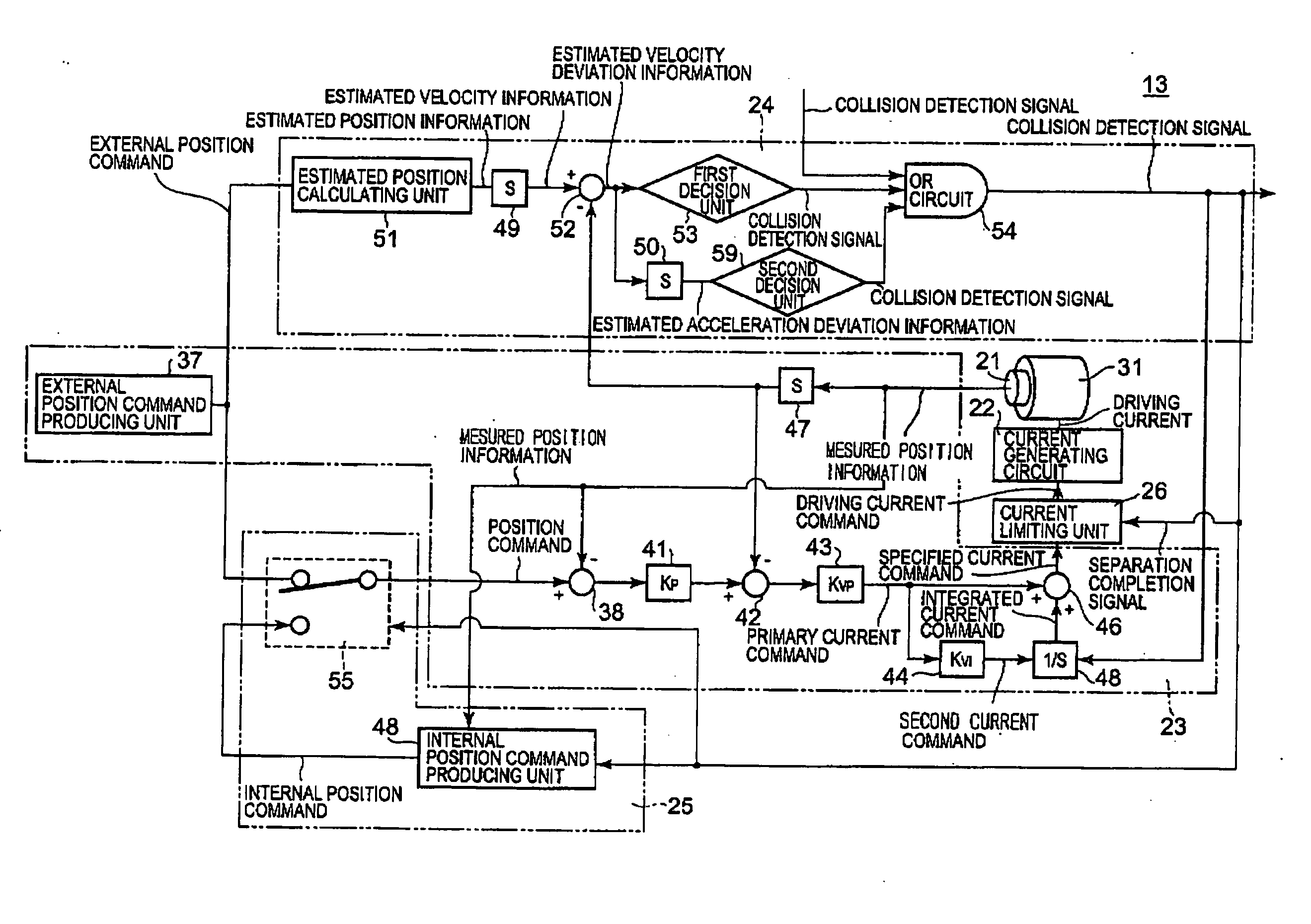
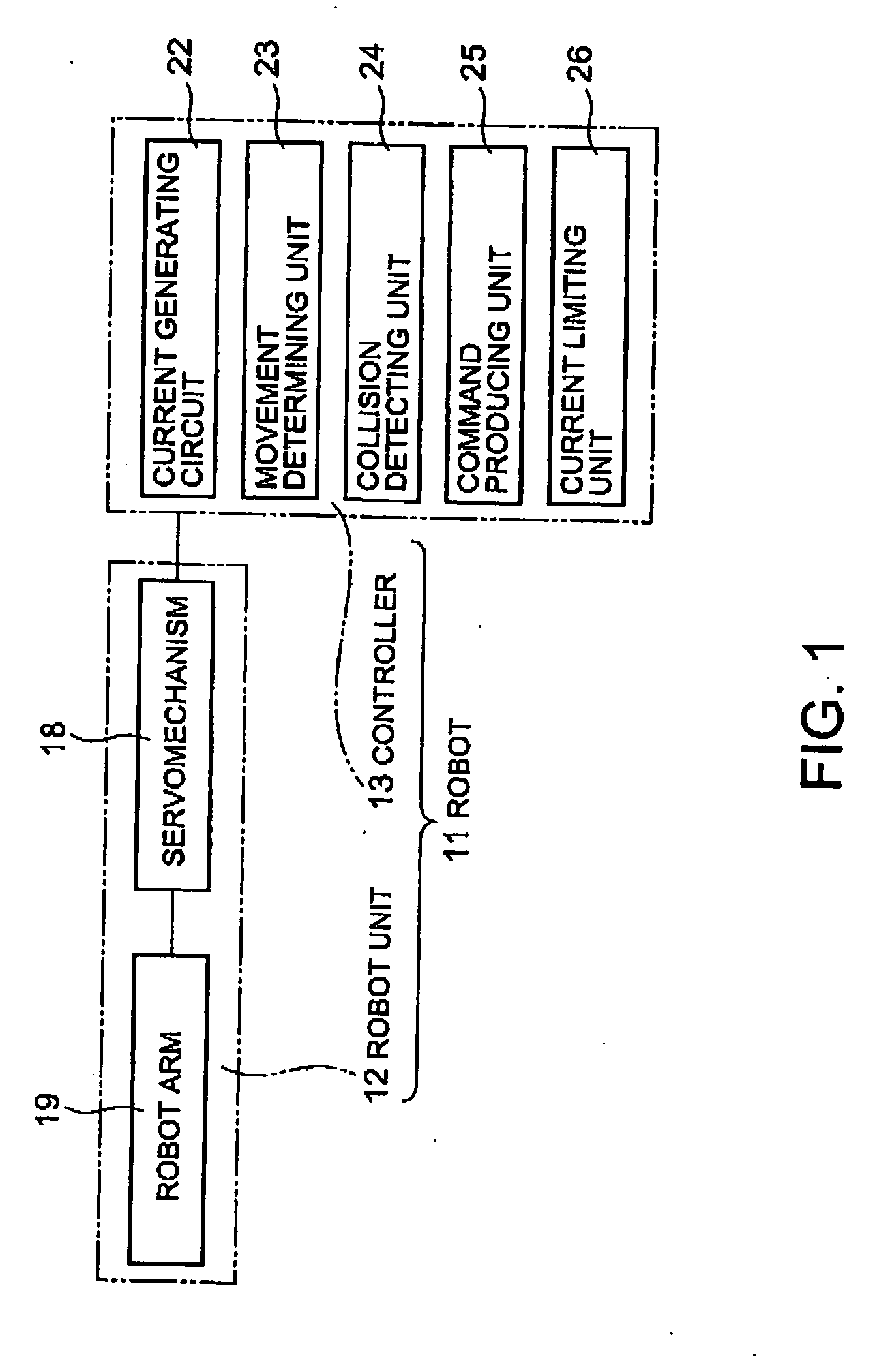
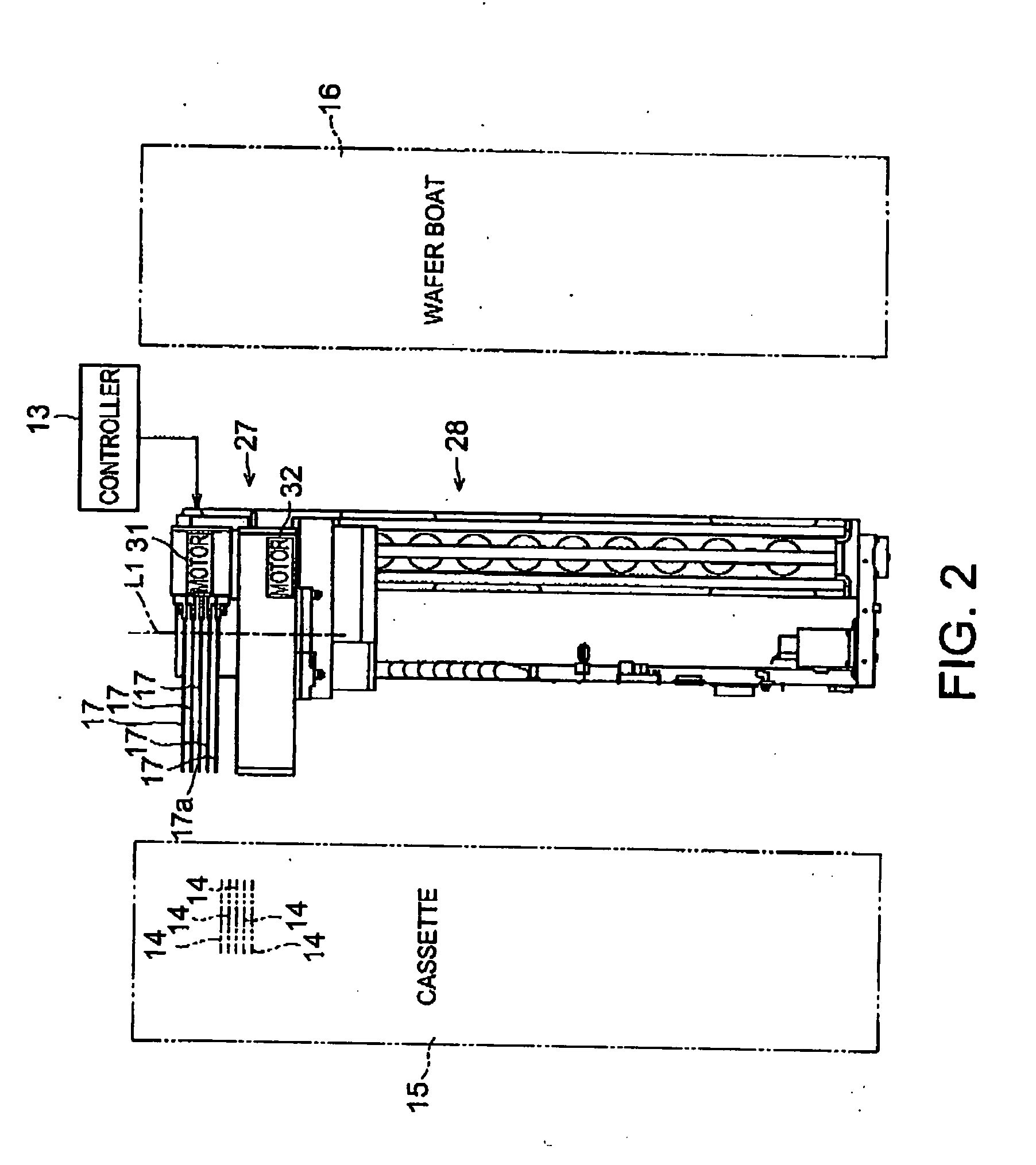
[0043] Referring to FIG. 1, a robot 11 in a preferred embodiment according to the present invention includes a robot unit 12, and a controller 13 for controlling the robot unit 12. The robot 11 carries a semiconductor wafer 14 (hereinafter, referred to simply as “wafer 14”) between a cassette 15 for holding wafers 14, and a wafer boat 16. The robot unit 12 includes a robot arm provided with hands 17, namely, movable bodies, and a servomechanism 18, namely, a driving mechanism. The robot arm 19 is movable. The servomechanism 18 is controlled by the controller 13 to-move the hands 17 by driving the robot arm 19 for movement.

[0044] The controller 13 controls the servomechanism 18 when the collision of the hand 17 with an obstacle is detected to suppress damage to component members caused by collision to the least possible extent. The obstacle is an object with which the hand 17 collides undesirably. For example, the obstacle is a wafer 14; there is a high possibility that the hand 17 ...


PUM


Abstract

A driving mechanism controller and a driving mechanism control method reduce damage to members caused by a collision. A command producing unit produces, upon the perception of the collision of a hand with an obstacle, a reversing signal for reversing a moving direction in which the hand is being moved by a motor and a position maintaining command requesting maintaining the hand at a position with respect to a direction perpendicular to the moving direction to which the hand has been displaced by the collision. After the detection of the collision of the hand with the obstacle, the hand is retracted maintaining the hand at the position to which the hand has been dislocated by the collision to separate the hand from the obstacle. Thus a pushing force exerted by the hand on the obstacle in the direction perpendicular to the moving direction is suppressed while the hand is separated from the obstacle.

Description

BACKGROUND OF THE INVENTION [0001] 1. Field of the Invention [0002] The present invention relates to a driving mechanism controller and a driving mechanism control method for controlling a driving mechanism when a moving unit driven by the driving mechanism collides with an obstacle. [0003] 2. Description of the Related Art [0004] A servomotor control method disclosed in, for example, JP-A 2001-117618 (Patent document 1) supplies a current to a servomotor so as to reverse torque that has been exerted on a hand upon the detection of the collision of the hand with an obstacle. The direction of motion of the hand is reversed by thus reversing the torque exerted on the hand to avoid pressing the hand further against the obstacle so that damage to the component members caused by collision may be limited to the least possible extent. [0005]FIG. 11 is a view of assistance in explaining the operation of a carrying robot 2 for carrying semiconductor wafers (hereinafter, referred to simply as...

Claims


Application Information

Patent Timeline
IPC IPC(8): B25J5/00G06F19/00B25J13/00B25J19/00B25J19/06G05B19/4062
CPCB25J9/1676G05B2219/49155G05B19/4061
Inventor YOSHIDA, MASAYAGOTO, HIROHIKO
Owner KAWASAKI HEAVY IND LTD
Why Eureka
Try Eureka