

Impedance matching apparatus
- Summary
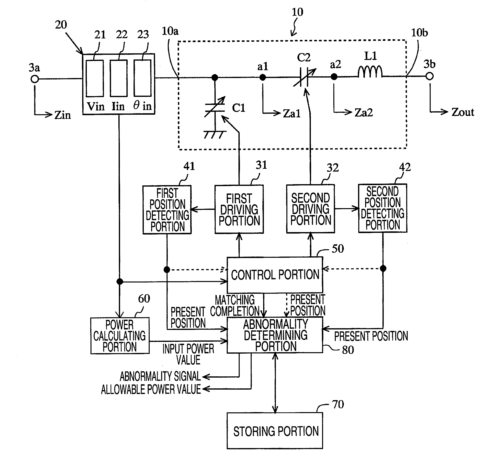
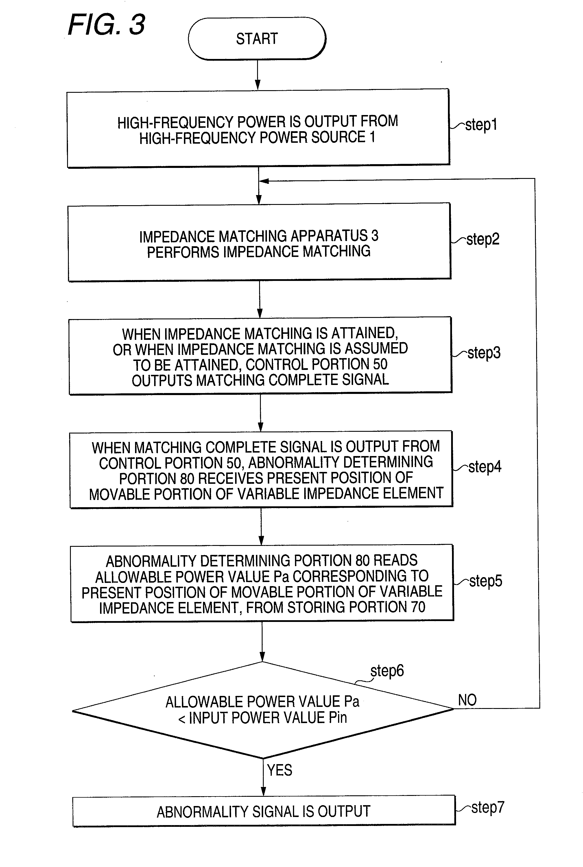
- Abstract
- Description
- Claims
- Application Information
AI Technical Summary
Benefits of technology
Problems solved by technology
Method used
Image

Examples
second embodiment
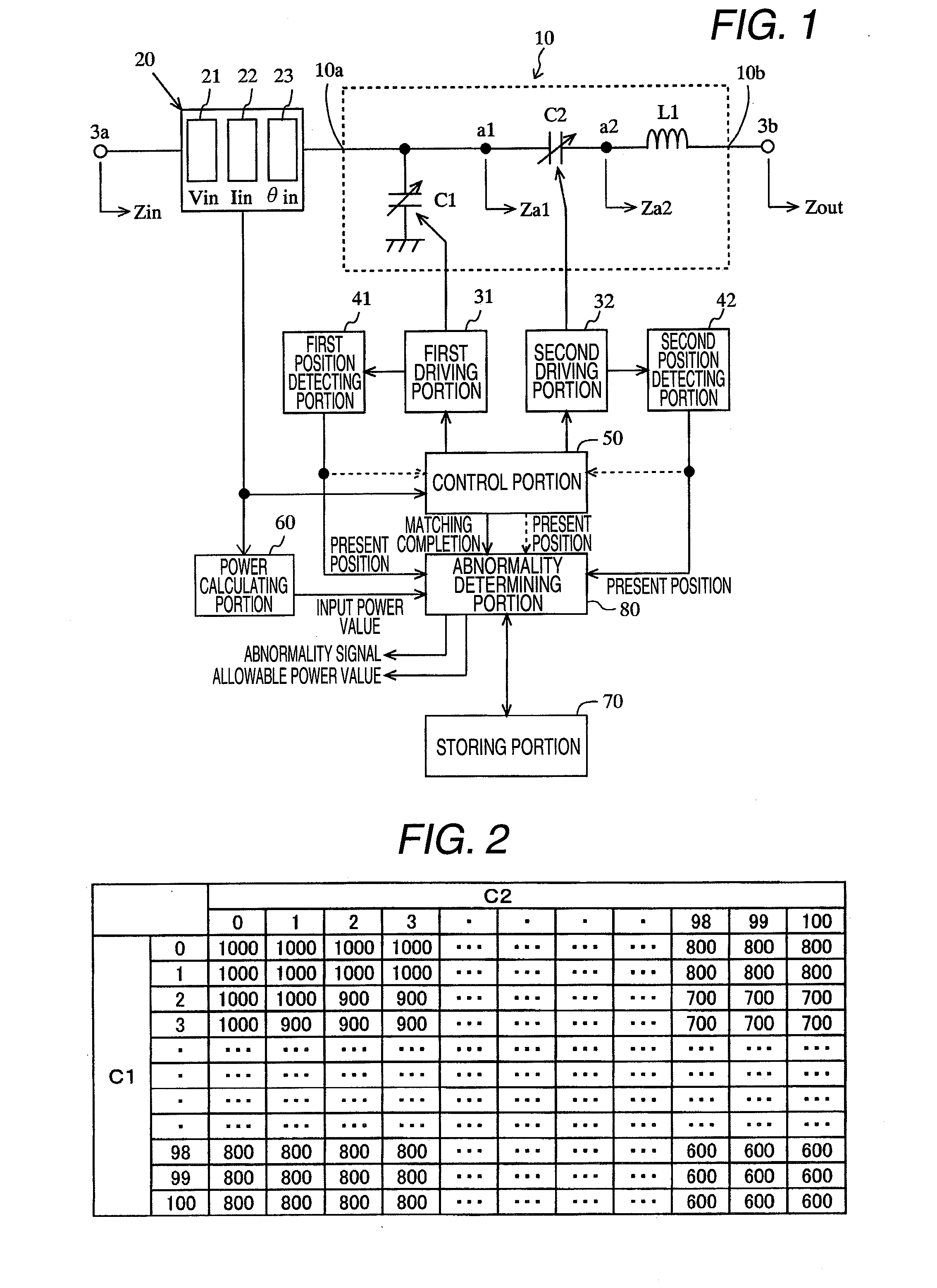
[0128]The storing portion 70 which has been described with reference to FIG. 2 previously stores, for all of the positions which can be taken by the movable portion of the variable impedance element or the combined positions of all of the positions which can be taken by the respective movable portions of the plural variable impedance elements, allowable power values Pp corresponding to the respective positions in an associated manner with the positions of the movable portion. As shown in FIG. 4, however, allowable power values are stored for part of the positions which can be taken by the movable portion of the variable impedance element or combined positions of part of the positions which can be taken by the respective movable portions of the variable impedance elements. This case will be described with reference to FIG. 4.
[0129]FIG. 4 shows another example of allowable power values Pp stored in the storing portion 70.
[0130]As shown in FIG. 4, even when the movable portion of the v...
PUM
 Abstract
Description
Claims
Application Information