Tone Correction Apparatus, Mobile Terminal, Image Capturing Apparatus, Mobile Phone, Tone Correction Method and Program

a tone correction and tone technology, applied in image enhancement, color signal processing circuits, instruments, etc., can solve the problems of imposing a limit in improving the local contrast in limiting the backlight correction effect for a bright region or a dark region as a whole, and achieving good tone correction results. , the effect of improving the local contras

Inactive Publication Date: 2007-10-04
MITSUBISHI ELECTRIC CORP
View PDF12 Cites 58 Cited by
  • Summary
  • Abstract
  • Description
  • Claims
  • Application Information

AI Technical Summary

Benefits of technology

[0016] 1) An image area is divided into a plurality of local region (e.g., blocks), and then, the amount of change from an average luminance level of a local region to a luminance level after correction is controlled by the average luminance level of the local region. This achieves an effect of obtaining a good tone correction result as a whole in the entirety of a part in which the same degree of tone level continues widely in area such as a bright region or a dark region while improving the local contrast.
[0017] 2) The average luminance level of each local r

Problems solved by technology

However, in the case of applying the aforementioned conventional technique for correcting tones of an image, the “histogram equalization method” or “local contrast correction method”, directly to backlight correction, a problem of imposing a limit in improving the local contrast in a bright region or a dark region arises.
Therefore, there exists a limit in correction amount of a dark part of a bright region and a bright part of a dark region, which inevitably causes a limit in imp

Method used


Image

  • Tone Correction Apparatus, Mobile Terminal, Image Capturing Apparatus, Mobile Phone, Tone Correction Method and Program
  • Tone Correction Apparatus, Mobile Terminal, Image Capturing Apparatus, Mobile Phone, Tone Correction Method and Program
  • Tone Correction Apparatus, Mobile Terminal, Image Capturing Apparatus, Mobile Phone, Tone Correction Method and Program

Examples


embodiment 1

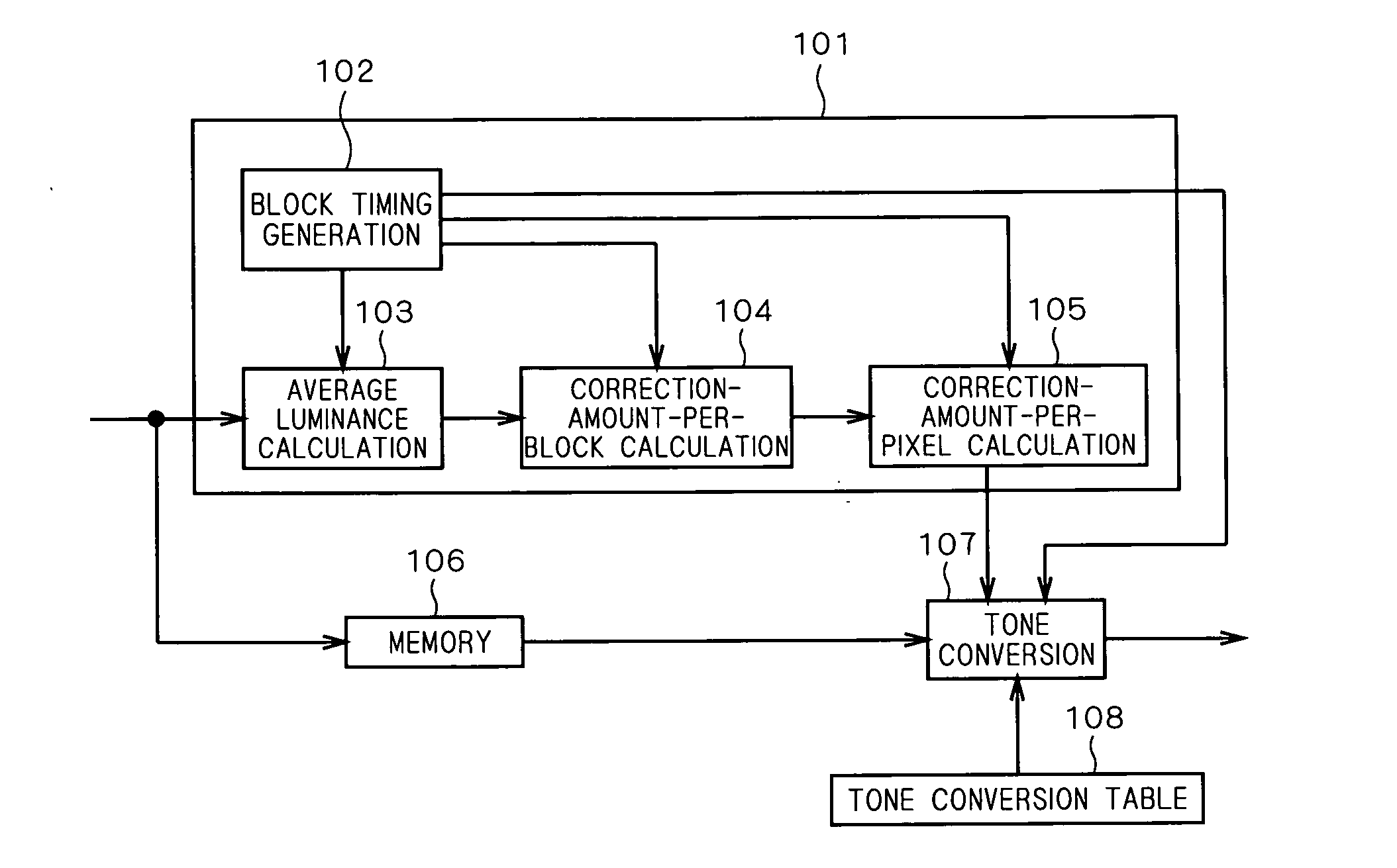
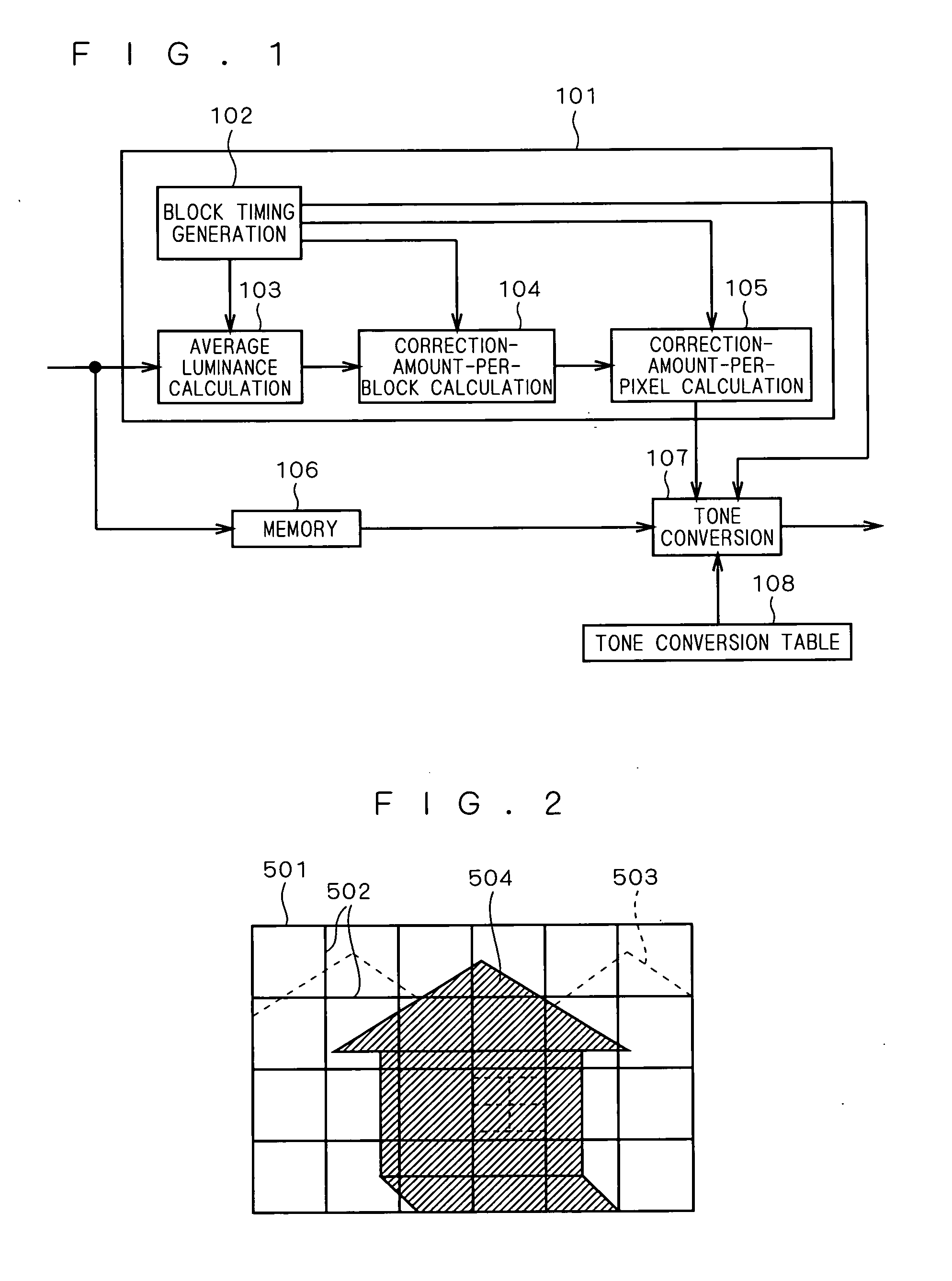
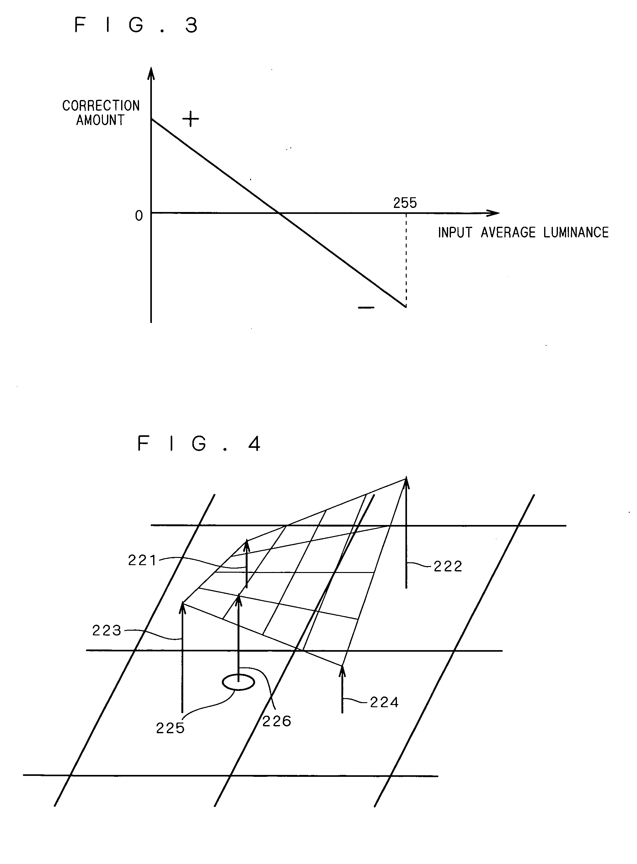
[0035] The present embodiment features dividing an image area into a plurality of blocks and then controlling the amount of change from an average luminance level of each local region divided as a block to a luminance level after correction by the average luminance level of the local region. Particularly, the present embodiment features controlling the average luminance level of each local region to increase when the average luminance level of the local region is relatively lower than a median value of all luminance tone levels. Conversely, the present embodiment features controlling the average luminance level of each local region to decrease when the average luminance level of the local region is relatively higher than the median value of all luminance tone levels. Further, the present embodiment features (1) controlling a correction amount in luminance correction of a local region to increase when the average luminance level of the local region is relatively lower than the median...

embodiment 2

[0063] The present embodiment features controlling the amount of change from the average luminance level of a local region to the luminance level after correction also by an average color-difference vector of the local region. Further, the present embodiment also features controlling the amount of change from the average luminance level of a local region to the luminance level after the correction so as to be small when the average color-difference vector of the local region is in the vicinity of almost skin color. Hereinafter, the features of the present embodiment will be described in detail on the basis of the accompanying drawings.

[0064]FIG. 8 is a diagram illustrating a block configuration of a tone correction apparatus according to the present embodiment. The configuration in FIG. 8 only differs from that of FIG. 1 in respective parts 109 and 110 in FIG. 8, and other elements are the same as corresponding elements in FIG. 1.

[0065] In FIG. 8, image data input to the tone corr...

embodiment 3

[0096] While Embodiment 1 has described the method of carrying out conversion with a conversion table in accordance with the number of levels of correction amount at the time of obtaining luminance data after correction from the correction amount per pixel, the present embodiment carries out conversion only using two types of conversion data tables.

[0097]FIG. 13 is a block configuration illustrating a tone correction apparatus according to this embodiment. The configuration of FIG. 13 differs from that of FIG. 1 in the device configuration of the part that carries out tone conversion. The part that carries out tone conversion is comprised of a first tone conversion part 107A having a first conversion table 108A, a second tone conversion part 107B having a second conversion table 108B and a tone interpolation part 107C. As shown in FIG. 14, the first conversion table part 108A is previously provided with a mapping curve 246 for the case in which the correction amount has its maximum...


PUM


Abstract

The present invention relates to a technique for correcting tones of a digitized image, for use in a mobile terminal or the like. The use of a conventional image tone correction technique to backlight correction imposes a limit on improvement in local contrast in a bright region or a dark region. According to the present invention, a block timing generation part (102) divides one image area into a plurality of blocks, an average luminance calculation part (103) calculates an average luminance level per block specified at the part 102, a correction-amount-per-block calculation part (104) calculates a direction of correction and a correction amount from an average luminance level per block, a correction-amount-per-pixel calculation part (105) interpolates the correction amount per block into the correction amount per pixel in that block, and a tone conversion part (107) reads out a final correction amount from a tone conversion table part (108), using the correction amount per pixel and luminance data of that pixel read out from a memory (106) as an address, to carry out tone conversion.

Description

TECHNICAL FIELD [0001] The present invention relates to a technique for correcting tones of a digitized image. BACKGROUND ART [0002] As a conventional technique for correcting tones of an image, the “histogram equalization method” of calculating a luminance value or density value of each pixel across an entire image area of an input image, creating a histogram showing the number of occurrences of pixels having the same tone value or pixels included in the same section obtained by division into less number of sections than a quantized number of tones, and carrying out tone correction processing across the entire image area such that the created histogram has an optimum shape is widely well known (cf. non-patent document 1). With this histogram equalization method of correcting tones of an image using the histogram, optimizing a tone distribution in the case where tones in the image area concentrate in a certain level can achieve improved tone characteristics of the whole image area. ...

Claims


Application Information

Patent Timeline
IPC IPC(8): G06T5/00H04N5/20G06T5/40H04N1/407H04N1/46H04N1/60H04N1/62H04N9/64
CPCG06T5/008G06T5/40H04N1/628H04N1/6027G06T2207/20032
Inventor ONO, YOSHIKISUGIYAMA, KAZUHIRO
Owner MITSUBISHI ELECTRIC CORP
Why Eureka
Try Eureka