Method for fabricating magnetic head

a magnetic head and head body technology, applied in the field of magnetic head fabrication, can solve the problems of difficult to obtain a stable device configuration, difficult to further downsize the core width, and limited stable core width to about 100 nm, and achieve stable device configuration, high precision, and high precision.

Inactive Publication Date: 2007-10-04
FUJITSU LTD
View PDF1 Cites 3 Cited by
  • Summary
  • Abstract
  • Description
  • Claims
  • Application Information

AI Technical Summary

Benefits of technology

[0010] An object of the present invention is to provide a method for fabricating a magnetic head having the CPP structure using a spin valve film, which can downsize and control with high precision the read core width and the read gap and can provide a stable device configuration.
[0011] According to one aspect of the present invention, there is provided a method for fabricating a magnetic head comprising the steps of: forming over a first region of a lower electrode a magnetoresistive effect film with a first polishing resistant film formed over an upper surface, the first polishing resistant film having a polishing selectivity to a magnetic material; forming a magnetic domain control film over an entire surface of the lower electrode including the first region; removing the magnetic domain control film over the magnetoresistive effect film by polishing with the first polishing resistant film as a stopper to leave the magnetic domain control film selectively in a second region adjacent to the first region; removing the first polishing resistant film; and forming an upper electrode over the magnetoresistive effect film from which the first polishing resistant film has been removed.
[0012] According to the present invention, in the method for fabricating a magnetic head using a magnetoresistive effect film, when a magnetic domain control film is deposited over the entire surface of a lower electrode with a magnetoresistive effect film formed on and is polished to thereby be left on both sides of the magnetoresistive effect film, a polishing resistant film is formed over the magnetoresistive effect film, whereby the polish of the region where the magnetoresistive effect film has been formed is prevented in the polishing. Thus, the read gap of the magnetic head can be controlled with high precision.

Problems solved by technology

In the current process, however, the stable core width is limited to about 100 nm due to limitations, restrictions, etc. of the photoresist forming process and the etching process.
It is very difficult to further downsize the core width.
It is difficult to obtain a stable device configuration.

Method used


Image

  • Method for fabricating magnetic head
  • Method for fabricating magnetic head
  • Method for fabricating magnetic head

Examples


first embodiment

A First Embodiment

[0019] The magnetic head and the method for fabricating the same according to a first embodiment of the present invention will be explained with reference to FIGS. 1 to 5D.

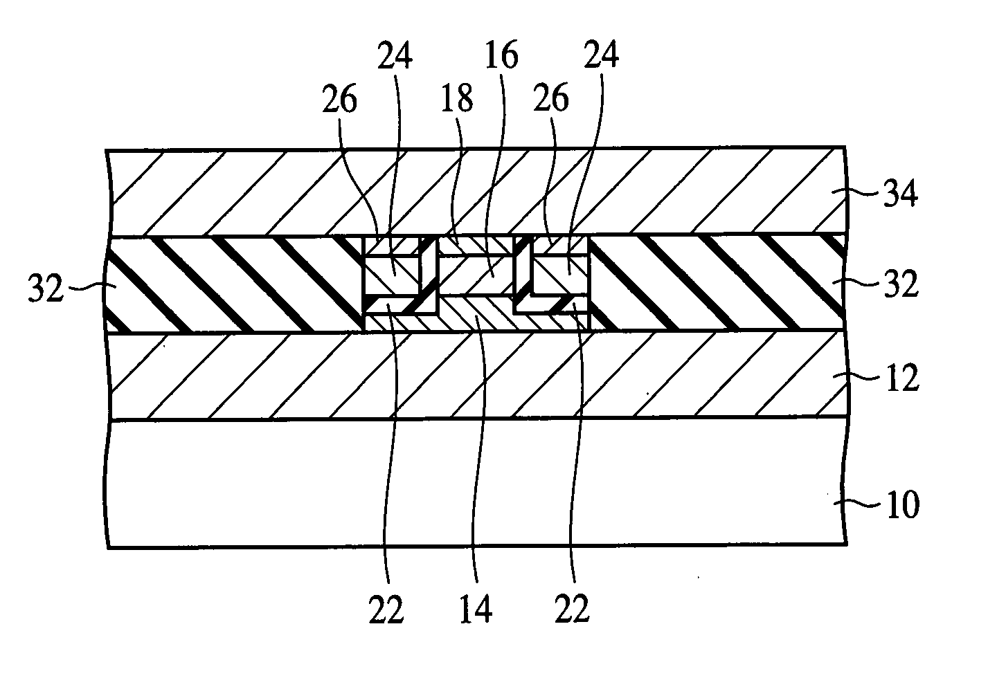
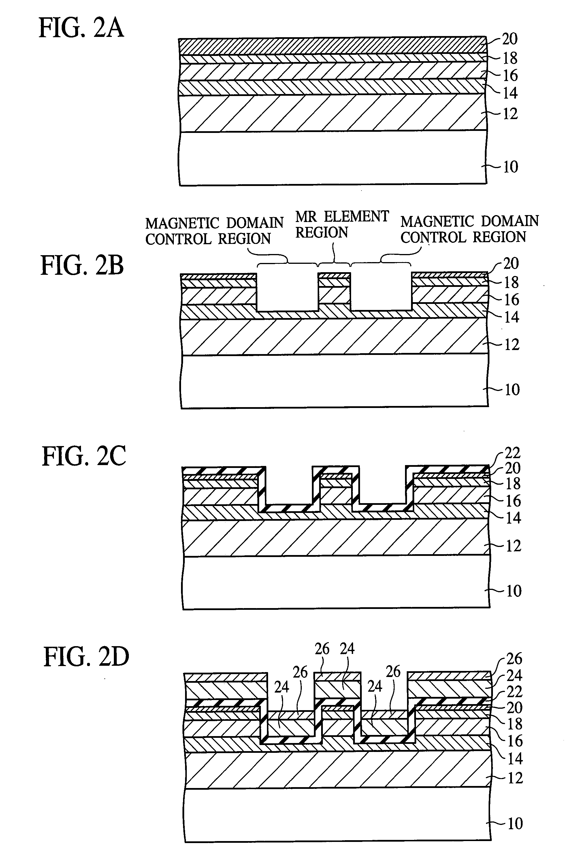
[0020]FIG. 1 is a front view of the magnetic head according to the present embodiment. FIGS. 2A to 4D are sectional views of the magnetic head according to the present embodiment in the steps of the method for fabricating the magnetic head. FIGS. 5A-5D are sectional views explaining the role of the polishing resistant film.

[0021] First, the structure of the magnetic head according to the present embodiment will be explained with reference to FIG. 1.

[0022] On a substrate 10, a lower electrode 12 which functions also as a lower shield is formed. On the lower electrode 12, an etching resistant film 14 of a conductive non-magnetic material, a magnetoresistive effect film 16 of the spin valve structure and a magnetoresistive effect film cap layer 14 of a conductive non-magnetic material are formed....

second embodiment

A Second Embodiment

[0061] The method for fabricating the magnetic head according to a second embodiment of the present invention will be explained with reference to FIGS. 6A to 7C. The same members of the present embodiment as those of the magnetic head and the method for fabricating the same according to the first embodiment shown in FIGS. 1 to 4D are represented by the same reference numbers not to repeat or to simplify their explanation.

[0062]FIGS. 6A to 7C are sectional views of the magnetic head according to the present embodiment in the steps of the method for fabricating the magnetic head.

[0063] In the present embodiment, another method for fabricating the magnetic head according to the first embodiment shown in FIG. 1 is explained.

[0064] First, in the same way as in the method for fabricating the magnetic head according to the first embodiment, which is shown in FIGS. 2A to 2D, the lower electrode 12, the etching resistant film 14, the magnetoresistive effect film 16, the...

third embodiment

[0077] The magnetic recording device according to a third embodiment of the present invention will be explained with reference to FIGS. 8 and 9. The same members of the present embodiment as those of the magnetic head according to the first and the second embodiments shown in FIGS. 1 to 7C are represented by the same reference numbers not to repeat or to simplify their explanation.

[0078]FIG. 8 is a diagrammatic plan view of the magnetic recording device according to the present embodiment. FIG. 9 is a front view of the magnetic head of the magnetic recording device according to the present embodiment.

[0079] First, the structure of the magnetic recording device according to the present embodiment will be explained with reference to FIG. 8.

[0080] The magnetic recording device 40 according to the present embodiment includes a box body 42 defining, e.g., a lengthy cuboid interior space. The housing space accommodates one or more magnetic discs 44 as the recording media. The magnetic ...


PUM

PropertyMeasurementUnit
widthaaaaaaaaaa
thicknessaaaaaaaaaa
thicknessaaaaaaaaaa

Abstract

The method for fabricating the magnetic head comprises the step of forming over a lower electrode a magnetoresistive effect film 16 with a polishing resistant film 20 formed over the upper surface, the step of forming a magnetic domain control film 24 over the entire surface of the lower electrode 12 including a region where the magnetoresistive effect film 16 has been formed, the step of selectively removing the magnetic domain control film 24 over the magnetoresistive effect film 16 by polishing with the polishing resistant film 20 as the stopper, the step of removing the polishing resistant film 20, and the step of forming an upper electrode 34 over the magnetoresistive effect film 16, from which the polishing resistant film 20 has been removed.

Description

CROSS-REFERENCE TO RELATED APPLICATIONS [0001] This application is a continuation-in-part of Ser. No. 11 / 452,948, filed Jun. 15, 2006. [0002] This application is based upon and claims the benefit of priorities from the prior Japanese Patent Application No. 2006-087206, filed on Mar. 28, 2006, and the prior Japanese Patent Application No. 2007-036172, filed on Feb. 16, 2007, the entire contents of which are incorporated herein by reference.BACKGROUND OF THE INVENTION [0003] The present invention relates to a method for fabricating a magnetic head, more specifically, a method for fabricating a magnetic head having the CPP (Current Perpendicular to Plane) structure, which uses the so-called spin valve film and flows a sense current in film thickness-wise direction. [0004] A magnetoresistive effect element using a spin valve film has two magnetic layers one of which has the magnetization direction pinned by a one-direction anisotropic magnetic field, etc. with respect to an anti-ferroma...

Claims


Application Information

Patent Timeline
Patent Type & Authority Applications(United States)
IPC IPC(8): G11B5/127
CPCG11B5/3163G11B5/3906G11B5/3169G11B5/127G11B5/39
Inventor ENDO, HIROSHIWAKABAYASHI, YASUHIROEGUCHI, SHINYAMAMOTO, TAMOTSUYANO, EI
Owner FUJITSU LTD
Why Eureka
Try Eureka