Zero parts strain relief

a technology of parts and strain relief, applied in the direction of electrical apparatus construction details, electrical circuit non-printed electric components association, etc., can solve the problems of limiting the installation, servicing and future modification of component devices in the system, and it is usually difficult or impossible to integrate new technology developed by other manufacturers, and achieves the effect of restricting the removal of the printed circuit board

Inactive Publication Date: 2007-10-04
LEVITON MFG
View PDF31 Cites 13 Cited by
  • Summary
  • Abstract
  • Description
  • Claims
  • Application Information

AI Technical Summary

Benefits of technology

[0017]There is disclosed a base member for holding, without screws, a printed circuit board having conductive traces and electronic components and which can fit into an electric outlet box. The base member has walls which define a cavity where at least one wall of the cavity has a rib, the top of which functions as a stop for the printed circuit board. A cap having clips adapted to engage the walls of the cavity restricts removal of the printed circuit board when snapped into position on top of the printed circuit board. The cap conceals the electronics on the printed circuit board and...

Problems solved by technology

With this type of proprietary system, the installation, servicing and future modifications of the component devices in the system are restricted to a single manufacturer's product offering and technical capability.
In addition, it is usually very difficult or impossible to int...

Method used


Image

  • Zero parts strain relief
  • Zero parts strain relief
  • Zero parts strain relief

Examples


Embodiment Construction

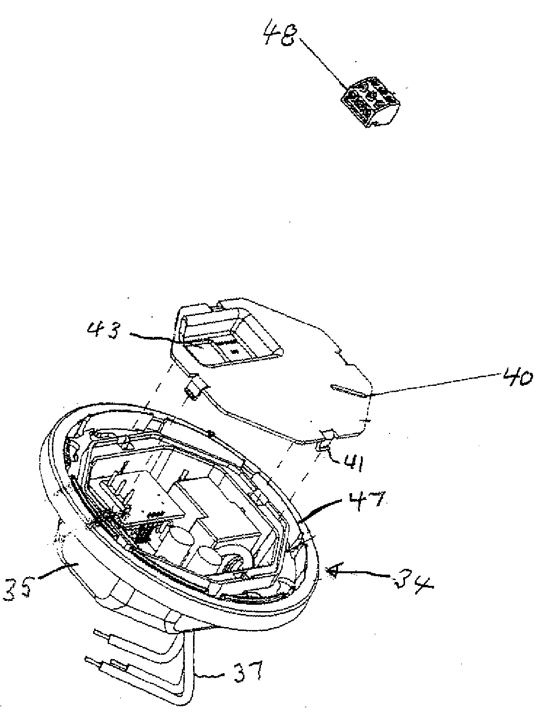
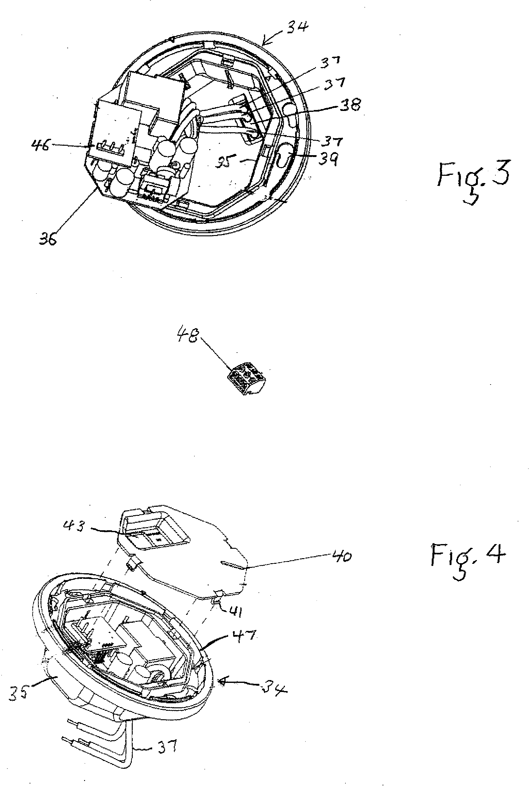
[0026]Referring to FIG. 3, there is shown a partial exploded perspective view of a base member 34 for receiving a printed circuit board 36 having conductive traces connecting electronic components on its top surface and conductive wires 37 which connect the electronic components on the printed circuit board to an external circuit. The base member 34 has an octagon shaped base 35 which is sized to fit within a 4 inch octagon electric outlet box and an outward extending cover plate member 37 which covers the space between the electric outlet box and the wall or ceiling when the base 35 is fitted into an electric outlet box. It is to be noted that the base member can be placed directly into an opening of a wall or ceiling, or in an outlet box that is in a wall or ceiling. The base member is adapted to be coupled to the electrical outlet box with screws which are inserted through mounting holes 39 and thread into threaded openings in the outlet box. The wires 37 from the printed circuit...


PUM


Abstract

There is disclosed a base member for holding, without screws, a printed circuit board having conductive traces and electronic components and which can fit into an electric outlet box. The base member has walls which define a cavity where at least one wall of the cavity has a rib, the top of which functions as a stop for the printed circuit board. A cap having snap features adapted to engage the walls of the cavity restricts removal of the printed circuit board when snapped into position on top of the printed circuit board. The cap conceals the electronics on the printed circuit board and has at least one rib on its bottom surface to apply pressure to the printed circuit board assembly to help hold it in place. An aperture in the cap provides access to a pin header which is electrically connected to the printed circuit board. A screw terminal block is provided to connect the terminals on the pin header to a sensor. The printed circuit board has one edge an open side hour glass shape aperture which provides strain relief for wires from the printed circuit board. Opposite ends of the aperture hold two wires captive and the space between the two wires holds captive a third wire.

Description

[0001]This application claims priority pursuant to 35 U.S.C. 119(e) from U.S. Provisional Application having Application No. 60 / 787,073 filed Mar. 29, 2006.BACKGROUND OF THE INVENTION[0002]1. Field of the Invention[0003]The present invention relates generally to an enclosure adapted to receive and hold captive a printed circuit board without requiring screws and where the printed circuit board is adapted to provide strain relief for wires from the printed circuit board.[0004]2. Description of the Related Art[0005]Today, automation systems which include sensors are being installed in more and more buildings, including both new construction and in structures that are being renovated and / or rebuilt. The incentives for putting automation systems into a building are numerous. High on the list are occupancy sensors to help reduce costs by turning off lights when a person leaves a room, more efficient use of energy, simplified control of the building systems, ease of maintenance and for ef...

Claims


Application Information

Patent Timeline
IPC IPC(8): H05K7/02
CPCH05K3/306H05K3/3405H05K3/3447H05K2201/10863H05K2201/09063H05K2201/09145H05K2201/10287H05K7/1417
Inventor ENGEL, JOHN B.NELSON, CLEVAN B.
Owner LEVITON MFG
Why Eureka
Try Eureka