Non-diagnostic stereoscopic x-ray tracking of moving objects in the context of radiotherapy and radiosurgery, with time-offset image recording

a technology of stereoscopic x-ray tracking and moving objects, applied in the field of x-ray tracking, can solve the problem of system exposure of patients to a relatively high radiation load, and achieve the effect of avoiding damage to healthy tissue and specifically irradiating diseased tissu

Active Publication Date: 2007-10-04
BRAINLAB
View PDF11 Cites 2 Cited by
  • Summary
  • Abstract
  • Description
  • Claims
  • Application Information

AI Technical Summary

Benefits of technology

[0005]A device and method in accordance with the invention can track a moving object within a patient, e.g., an object that changes its position with a patient's movement due to breathing. If, before therapy, imaging methods (e.g., CT, MR, etc.) are used to produce three-dimensional image recordings of the patient in the area around the target treatment region, wherein the object can also be seen or otherwise captured, the current location in three-

Problems solved by technology

Given the high scanning rates used, which are necessary to precisely track the movement, such systems expose the

Method used


Image

  • Non-diagnostic stereoscopic x-ray tracking of moving objects in the context of radiotherapy and radiosurgery, with time-offset image recording
  • Non-diagnostic stereoscopic x-ray tracking of moving objects in the context of radiotherapy and radiosurgery, with time-offset image recording
  • Non-diagnostic stereoscopic x-ray tracking of moving objects in the context of radiotherapy and radiosurgery, with time-offset image recording

Examples


Embodiment Construction

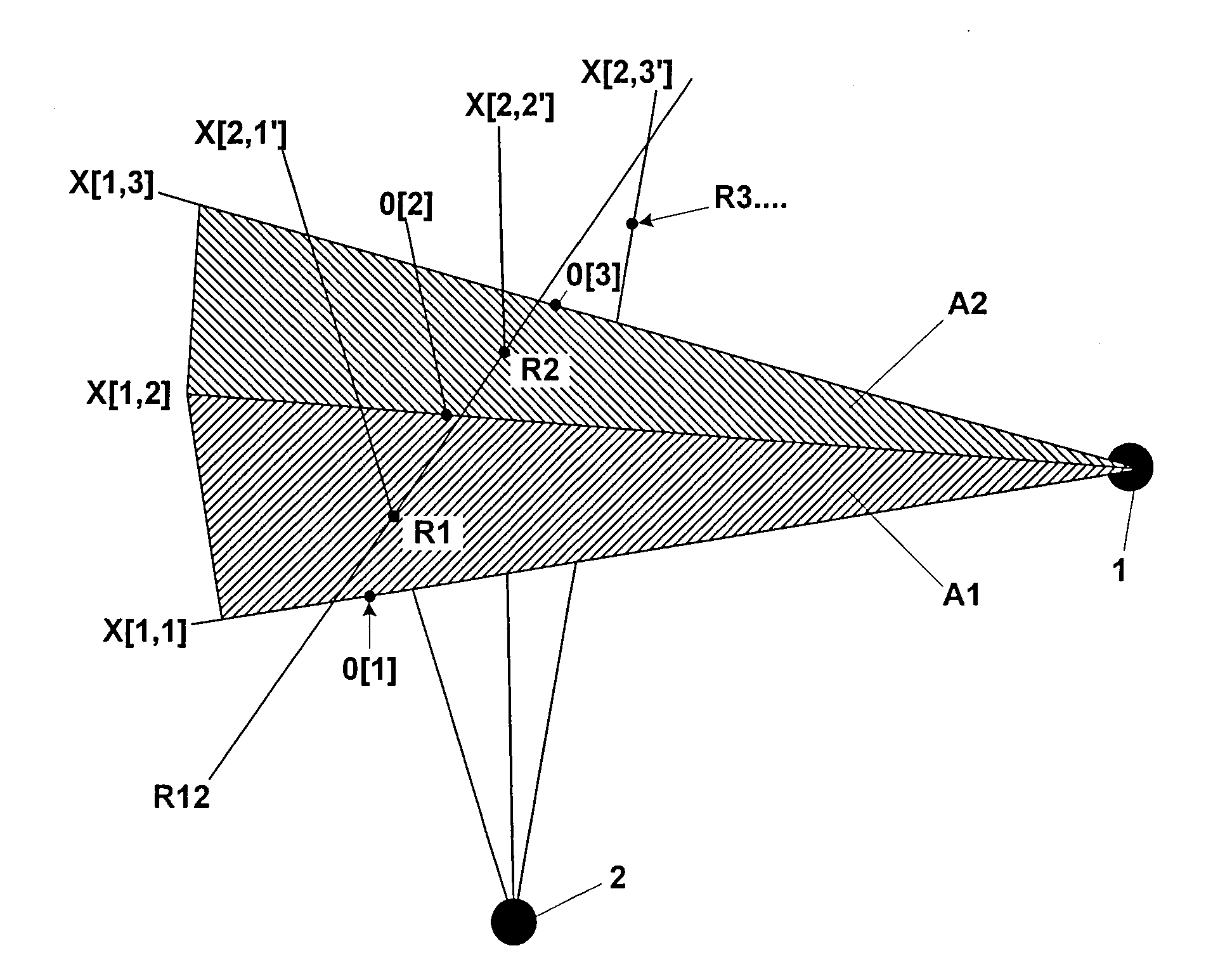
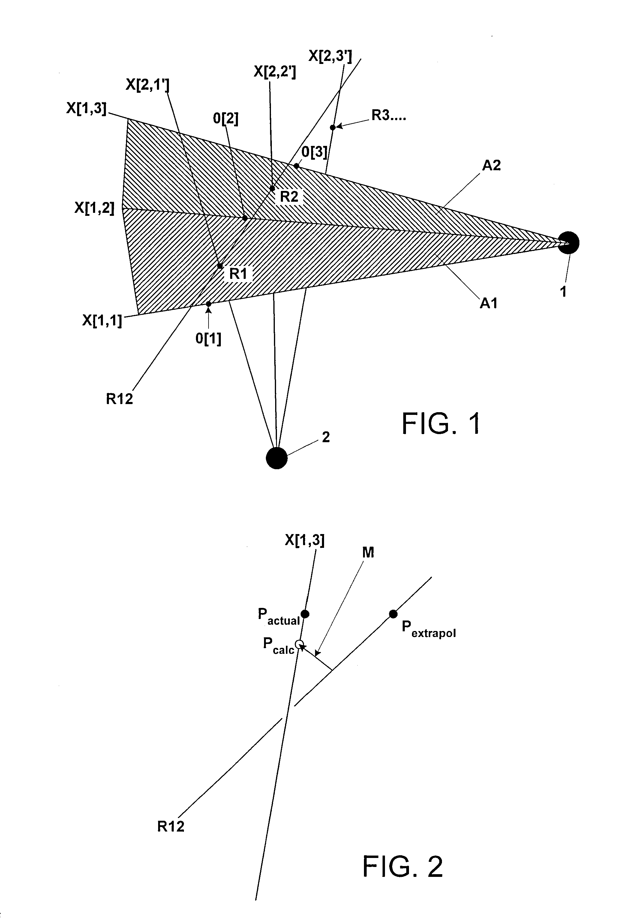
[0057]FIG. 1 shows two x-ray sources 1 and 2, and an object O that moves through a number of successive points in time, i.e., the object O[1] at Time 1, the object O[2] at Time 2 and the object O[3] at Time 3. The position of the object is tracked as follows:

[0058]At Time 1, a first x-ray image is produced using the x-ray source 1, and a viewing line X[1, 1] in this x-ray image passes through the object O[1]. The object then moves on and at Time 2 comes to the point at which it is shown by 0[2]. An x-ray image is in turn also produced at this point in time by the source 1, and the viewing line X[1, 2] is obtained.

[0059]Between Time 1 and Time 2 (in this example, after half the time has passed), i.e., at the intermediate point in time 1′, an x-ray recording is produced using the x-ray source 2 and having the viewing line X[2, 1′]. If the surface A1 between the viewing lines X[1, 1] and X[1, 2] is then calculated and / or spanned, it is also possible to calculate the point at which the ...


PUM


Abstract

A non-diagnostic, stereoscopic x-ray tracking apparatus and method for tracking moving objects in the context of radiotherapy and radiosurgery includes using two x-ray tubes to alternately and repeatedly record x-ray images of an object along two different viewing lines through the target area of an irradiating apparatus. The viewing lines intersect at a known angle, wherein an extrapolated object trajectory is ascertained by determining surfaces and intersecting points. Further, a minimum transversal from the object trajectory onto a current viewing line is ascertained, wherein the three-dimensional position of the tracked object is approximated at the point at which the object trajectory meets the viewing line.

Description

RELATED APPLICATION DATA[0001]This application claims priority of U.S. Provisional Application No. 60 / 745,032 filed on Apr. 18, 2006, which is incorporated herein by reference in its entirety.FIELD OF THE INVENTION[0002]The invention relates to the non-diagnostic, stereoscopic x-ray tracking of moving objects in the context of radiotherapy and radiosurgery. More specifically, the invention relates to x-ray tracking in which two x-ray tubes are used to repeatedly record x-ray images of an object along two different viewing lines through a target area of an irradiating apparatus, said viewing lines intersecting at a known angle.BACKGROUND OF THE INVENTION[0003]Real-time x-ray tracking of moving targets, for example implanted tracking markers, is known in principle in the context of radiotherapy and / or radiosurgery. Thus, for example, U.S. Pat. No. 5,207,223 describes a method and apparatus for selectively irradiating a target within a patient, wherein images of the target area and of ...

Claims


Application Information

Patent Timeline
IPC IPC(8): A61B6/02G21K4/00G03C9/00
CPCA61B6/022
Inventor ERBEL, STEPHAN
Owner BRAINLAB
Why Eureka
Try Eureka