
Vehicle visibility vest

a technology for vehicles and vests, applied in road signs, portable emergency signal devices, roads, etc., can solve the problems of reducing the use of these lights, affecting the safety of drivers, and consuming a limited amount of fuel, so as to reduce the risk of collisions, reduce the number of fatalities and injuries, and increase the visibility of vehicles.

Inactive Publication Date: 2007-10-04
ROCHE DAVID IAN +1
View PDF22 Cites 10 Cited by
  • Summary
  • Abstract
  • Description
  • Claims
  • Application Information

AI Technical Summary

Benefits of technology

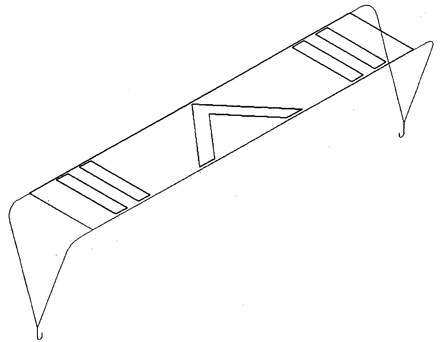
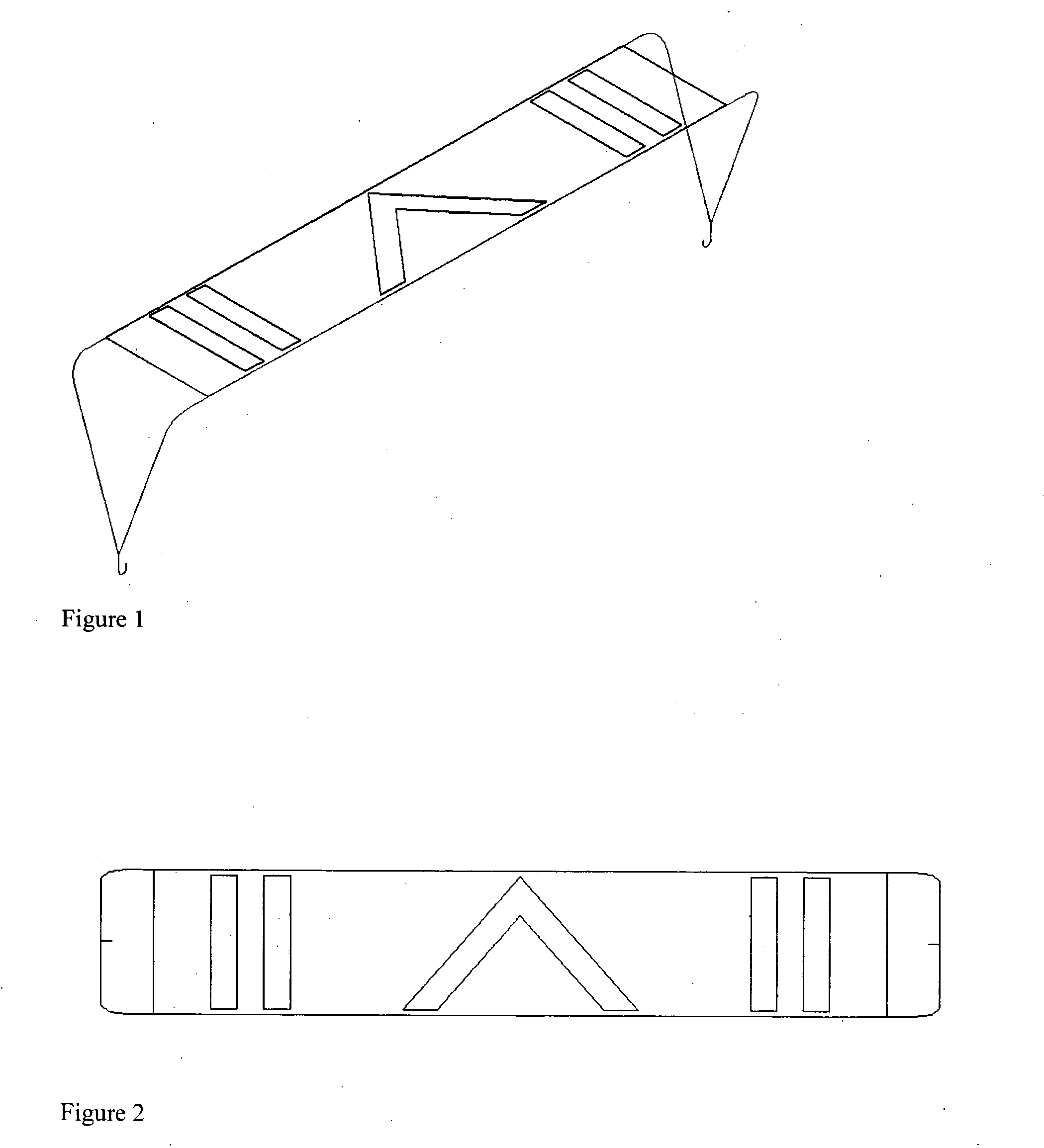
[0010]This invention takes the idea of high visibility clothing and applies it to a broken down vehicle. By utilizing existing materials in a different manner we can increase the visibility of vehicles that are in hazardous situations and in doing so reduce the risk of collisions and therefore reduce the number of fatalities and injuries that would result from these collisions.
[0011]Often increasing visibility in a breakdown situation involves utilizing battery power; headlights or hazard lights. Loss of battery power is often the cause of the breakdown thereby rendering use of these lights impossible. Motorists are also taught to use flares as a means of alerting others of their distress. This implies that you have flares with your vehicle that have not expired or at all, for that matter. If one does have a working flare, it will only burn for a limited amount of time, dependent upon weather, etc. Using this invention would solve both of these problems, as it is everlasting and highly visible day and night without being reliant upon battery power. This device is also completely safe and tightly secured, making it stable, unlike flares and common hazard triangles.

Problems solved by technology

Loss of battery power is often the cause of the breakdown thereby rendering use of these lights impossible.
If one does have a working flare, it will only burn for a limited amount of time, dependent upon weather, etc.

Method used


Image

  • Vehicle visibility vest
  • Vehicle visibility vest
  • Vehicle visibility vest

Examples


Embodiment Construction

[0018]The invention is constructed by using a rectangular background of fluorescent fabric that has stripes of retro-reflective tape attached in a distinctive pattern. A retroreflective material is one having the ability to return a substantial portion of incident light in the direction of origination of the light.

[0019]The background material is typically a colored fluorescent material that is highly conspicuous and emits optical radiation at wavelengths longer than those absorbed. Fluorescent material enhances daytime visibility, especially at dawn and dusk, and is usually lime-yellow, red or red-orange in color.

[0020]Retroreflection, as opposed to mirror reflection or diffuse reflection, occurs when a high percentage of radiant energy is returned back in the direction from which it came, and over a wide variety of angles from which the material is being struck. A retro-reflective material has the property to reflect light directly back to the light source through a wide range of ...


PUM


Abstract

A high visibility fluorescent fabric and retro-reflective tape banner to be attached to the rear of a vehicle in the event of a breakdown. It will raise visibility to approaching vehicular traffic thereby reducing the risk of collision and injury.

Description

CROSS-REFERENCE TO RELATED APPLICATIONS[0001]Not applicableSTATEMENT REGARDING FEDERALLY SPONSORED RESEARCH OR DEVELOPMENT[0002]Not applicableREFERENCE TO SEQUENCE LISTING, A TABLE, OR A COMPUTER PROGRAM LISTING COMPACT DISC APPENDIX[0003]Not applicableFIELD OF THE INVENTION[0004]This invention relates to the use of existing high visibility fluorescent fabric and reflective tape commonly used in safety vests / clothing in a design for use in the event of a breakdown involving motor vehicles.BACKGROUND OF THE INVENTION[0005]The combination of fluorescent fabric and retro-reflective tape is widely used to produce high visibility safety clothing for workers in high risk environments, in particular for workers involved in highway construction. This safety clothing is worn because it will increase the visibility of the wearer and therefore reduce the risks of collision from passing traffic.[0006]In recognition of this problem various standards have been proposed and adopted addressing the ...

Claims


Application Information

Patent Timeline
IPC IPC(8): E01F9/00
CPCB60Q7/005
Inventor ROCHE, DAVID IANECIN, BILFER
Owner ROCHE DAVID IAN
Learn More