Toolholder with chip ejection segment thereupon

a toolholder and chip technology, applied in the field of toolholders, can solve problems such as chip interference with metalworking operations

Active Publication Date: 2007-10-04
KENNAMETAL INC
View PDF24 Cites 28 Cited by
  • Summary
  • Abstract
  • Description
  • Claims
  • Application Information

AI Technical Summary

Problems solved by technology

The formation of the chips not only provides an indication of the efficiency of the metalcutting operation, but furthermore, if the chips are not properly evacuated

Method used


Image

  • Toolholder with chip ejection segment thereupon
  • Toolholder with chip ejection segment thereupon
  • Toolholder with chip ejection segment thereupon

Examples


Embodiment Construction

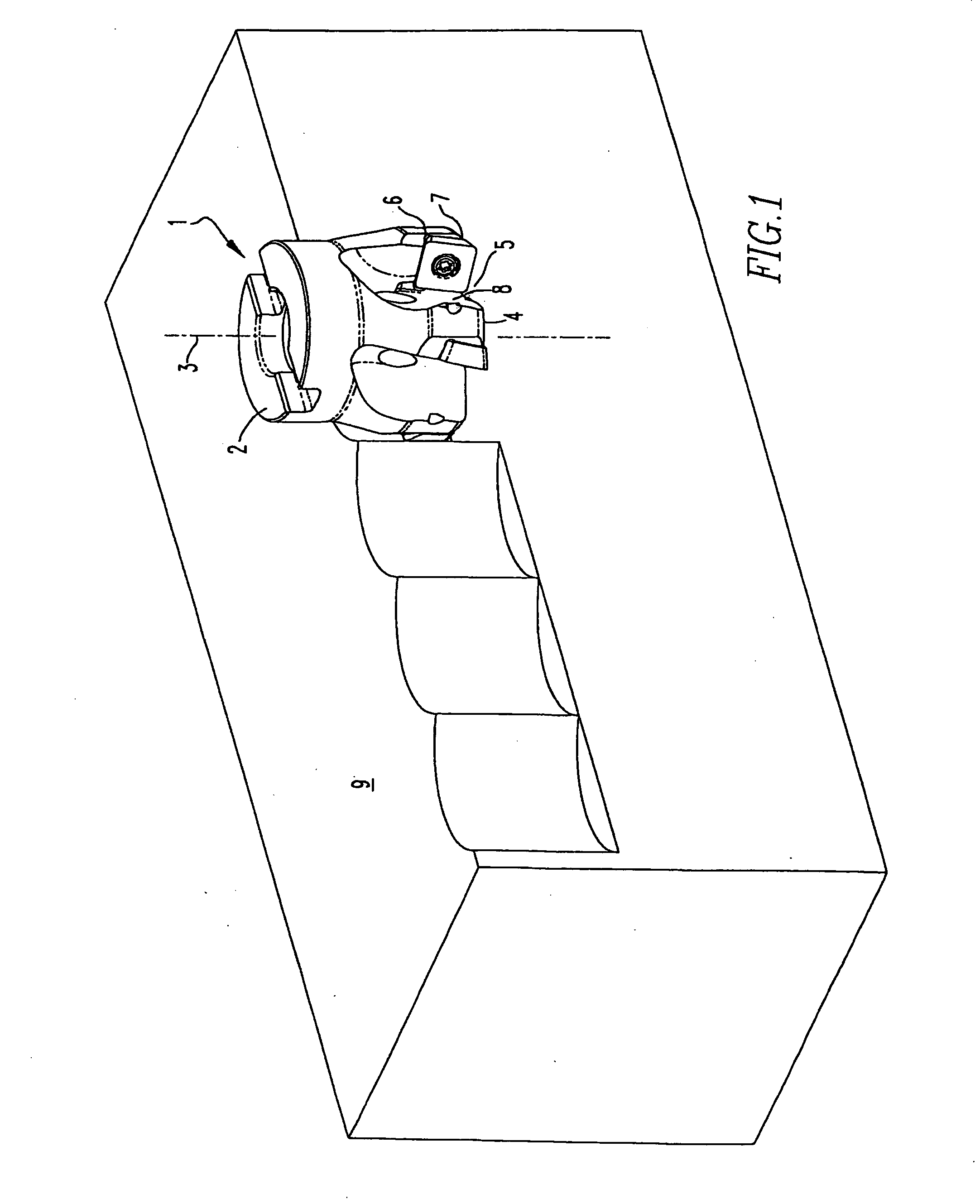
[0020]FIG. 1 is prior art and illustrates a milling cutter 1 with a body 2 extending along a longitudinal axis 3. The body 2 has a first end 4 with a recess 5 extending therein. The recess 5 has an insert pocket 6 for receiving a cutting insert 7. There is at least one wall 8 adjacent to the pocket 6. In general, the purpose of the recess 5 is to provide clearance for chips that are produced during a metalworking operation upon the workpiece 9 as the body 2 rotates about the longitudinal axis 3.

[0021] The inventors have discovered that chip ejection from the work area may be influenced by features that may be present in one or more walls within the recess 5.

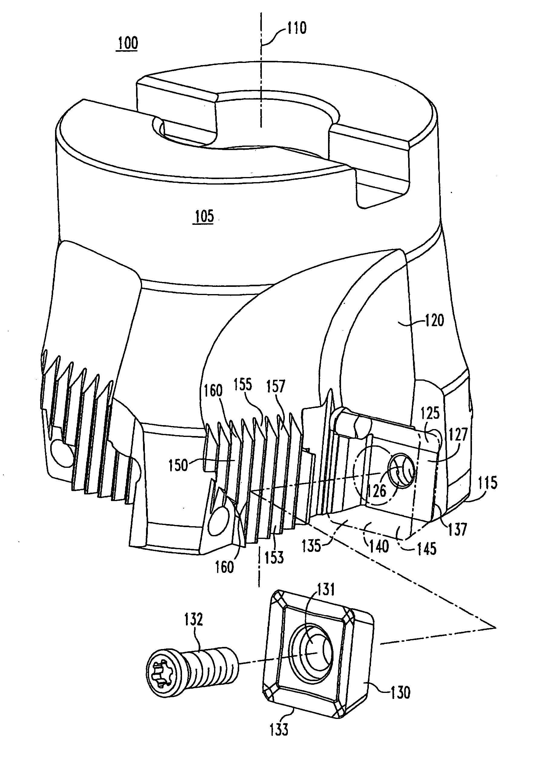
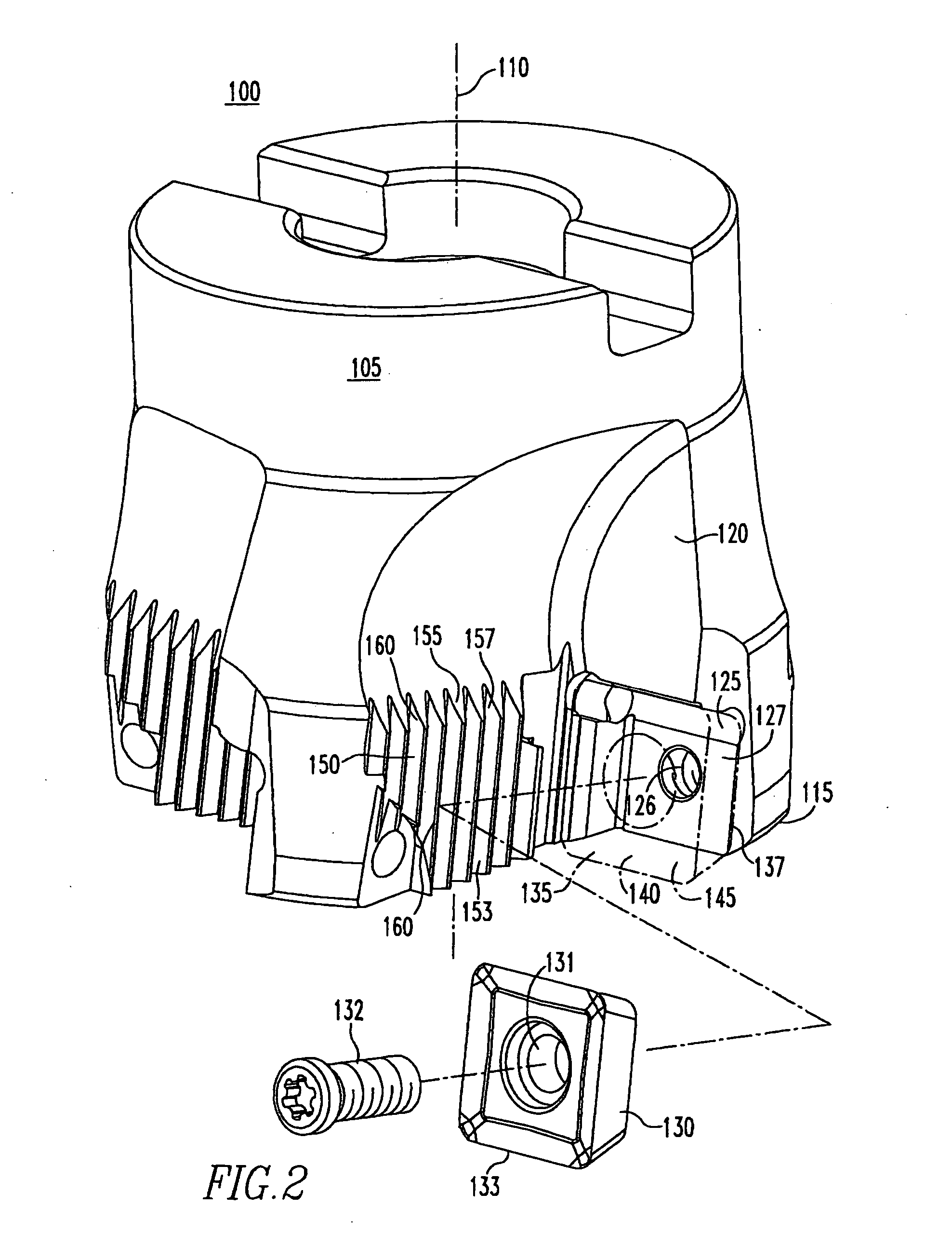
[0022] In particular, directing attention to FIGS. 2-5, a toolholder 100 is comprised of a body 105 which extends along a longitudinal axis 110 and has a first end 115. A recess 120 extends into the first end 115. The recess 120 has an insert pocket 125 adapted to receive a cutting insert 130. The cutting insert 130 may have a ...


PUM

PropertyMeasurementUnit
Angleaaaaaaaaaa
Angleaaaaaaaaaa
Angleaaaaaaaaaa

Abstract

A toolholder for use in a metalworking operation, with a body extending along a longitudinal axis and a recess extending within the first end of the body. Adjacent an insert pocket adapted to receive a cutting insert in the recess is at least one wall with a portion having a surface with multiple interruptions to form a chip ejection segment. The chip ejection segment may be an integral part of the toolholder body or may be a discrete piece removably attached to the toolholder body. A method of imparting to a toolholder such a chip ejection segment is also disclosed.

Description

BACKGROUND OF THE INVENTION [0001] 1. Field of the Invention [0002] The present invention is directed to a toolholder for use in metalworking operations whereby a chip ejection segment is mounted upon or is an integral part of the toolholder. [0003] 2. Description of Related Art [0004] A primary object of a metalworking operation is the shaping of a workpiece. Much attention is paid to the formation of metallic chips during the machining process, even though the chip is a waste product. The formation of the chips not only provides an indication of the efficiency of the metalcutting operation, but furthermore, if the chips are not properly evacuated from the working region, the chips may interfere with the metalworking operation by scraping against a finished metal surface or by accumulating in the working area. [0005] It is the object of the invention to provide a mechanism for effectively ejecting chips formed during a metalworking operation from the working area. SUMMARY OF THE IN...

Claims


Application Information

Patent Timeline
IPC IPC(8): B23C5/00B23B27/22
CPCB23B27/22B23C5/006B23C2230/04B23C2260/80Y10T408/909Y10T407/1908Y10T407/2202Y10T82/10Y10T407/2268Y10T407/24Y10T407/118Y10T407/1906B23C5/00
Inventor WAGGLE, JAMES M.MCNAMARA, DENNIS W.DUDZINSKY, RONALD L.MEENAN, LARRY R.MORRISON, LEWIS RAY
Owner KENNAMETAL INC
Why Eureka
Try Eureka