Pulley assembly and pulley usable therefor

a technology of pulleys and pulleys, which is applied in the direction of gearing, gearing elements, hoisting equipments, etc., can solve the problems of increasing the temperature of bearings, increasing the risk of bearing deterioration, so as to achieve the effect of further reducing the generation of wind nois

Inactive Publication Date: 2007-10-04
JTEKT CORP
View PDF6 Cites 36 Cited by
  • Summary
  • Abstract
  • Description
  • Claims
  • Application Information

AI Technical Summary

Benefits of technology

[0019] In this embodiment, since front/rear faces of the plurality of spokes are positioned on one identical imaginary surface of revolution centered on the axis of t

Problems solved by technology

However, this conventional pulley assembly has a problem that because of a difference in coefficient of thermal expansion between the material of the outer ring and the material of the pulley, creeps may occur between the outer ring of the bearing and the pulley due to a difference in thermal expansion resulting from temperature increases.
Besides, because of poor heat radiation of the resin-made pulley, heat such as heat generated in the bearing and frictional heat generated between the resin-made pulley and the belt is

Method used


Image

  • Pulley assembly and pulley usable therefor
  • Pulley assembly and pulley usable therefor
  • Pulley assembly and pulley usable therefor

Examples


first embodiment

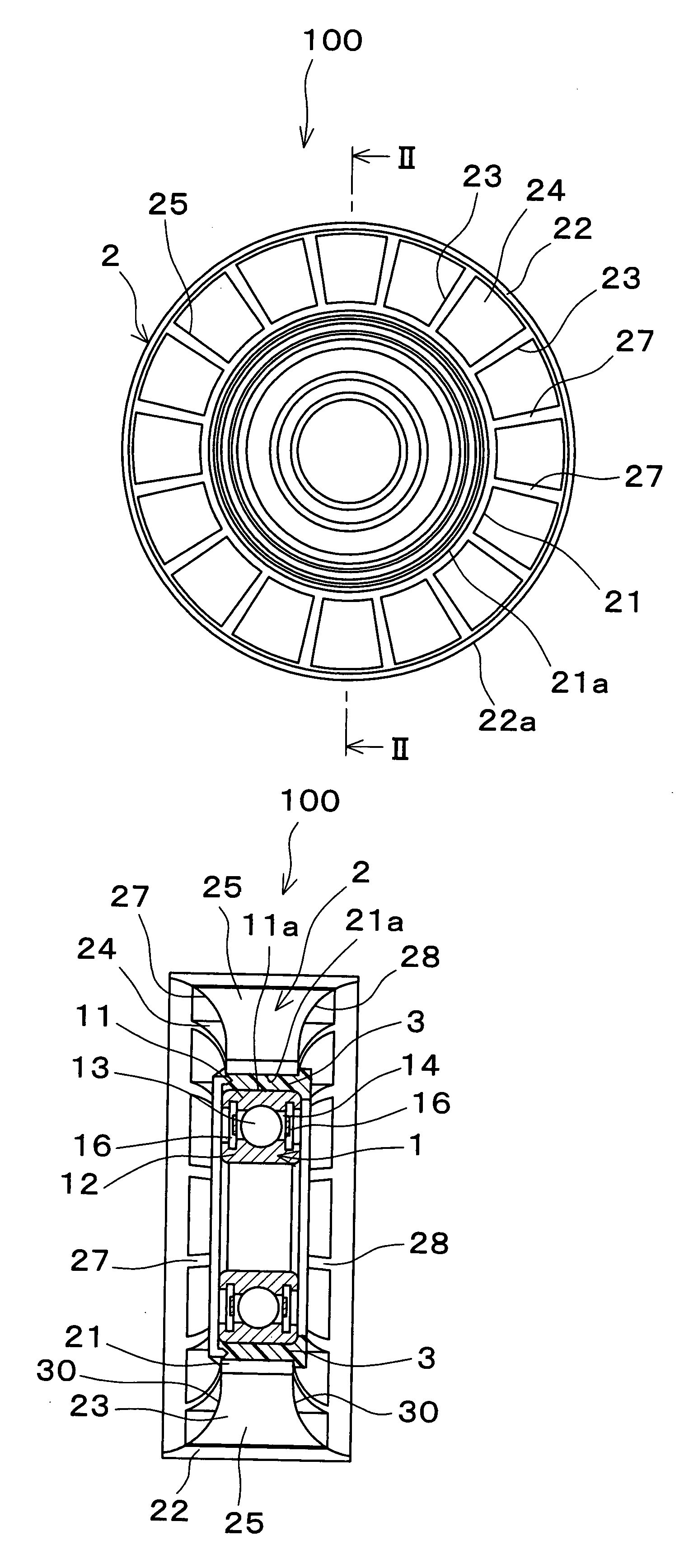
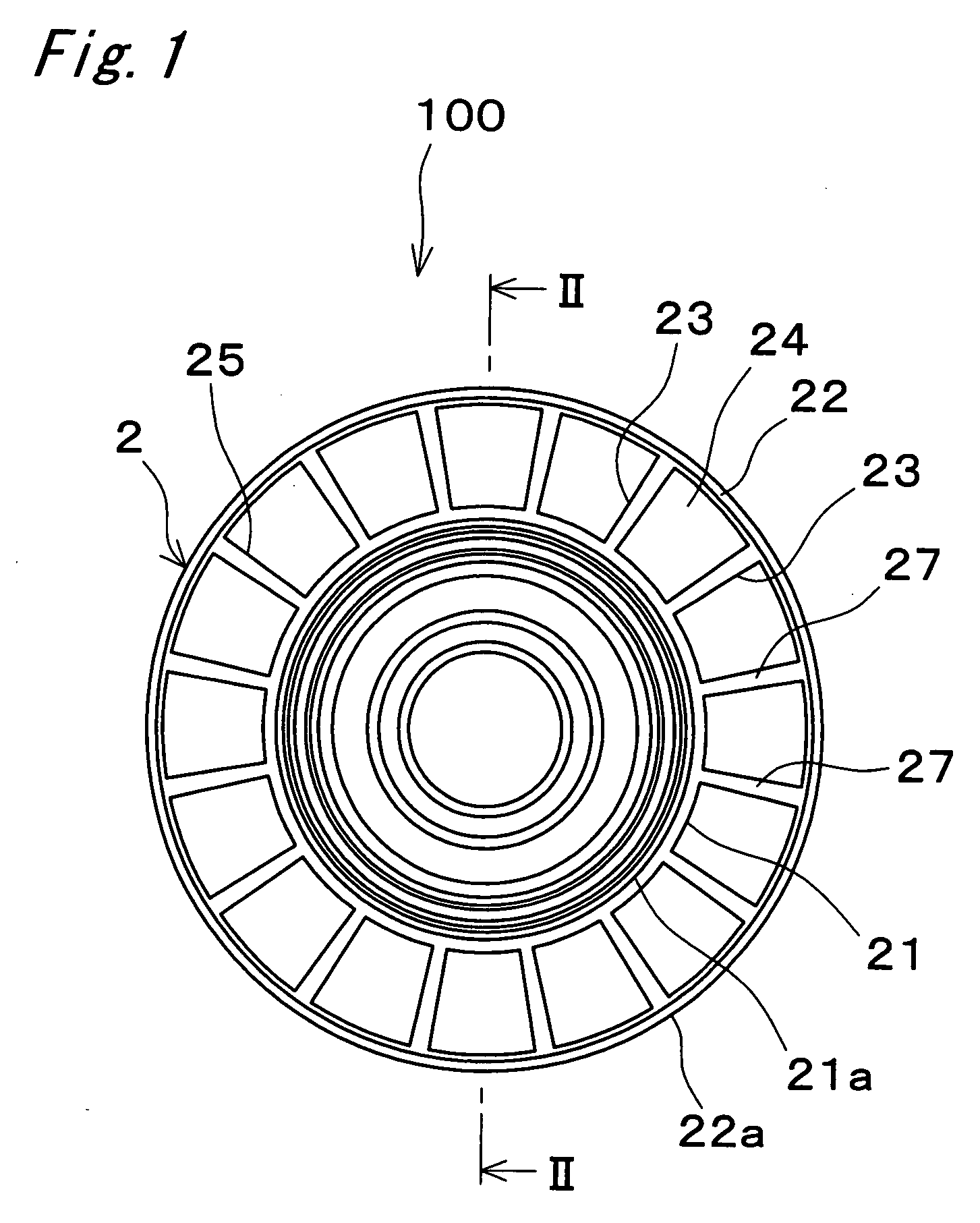
[0023]FIG. 1 is a front view of a pulley assembly 100 according to the present invention.

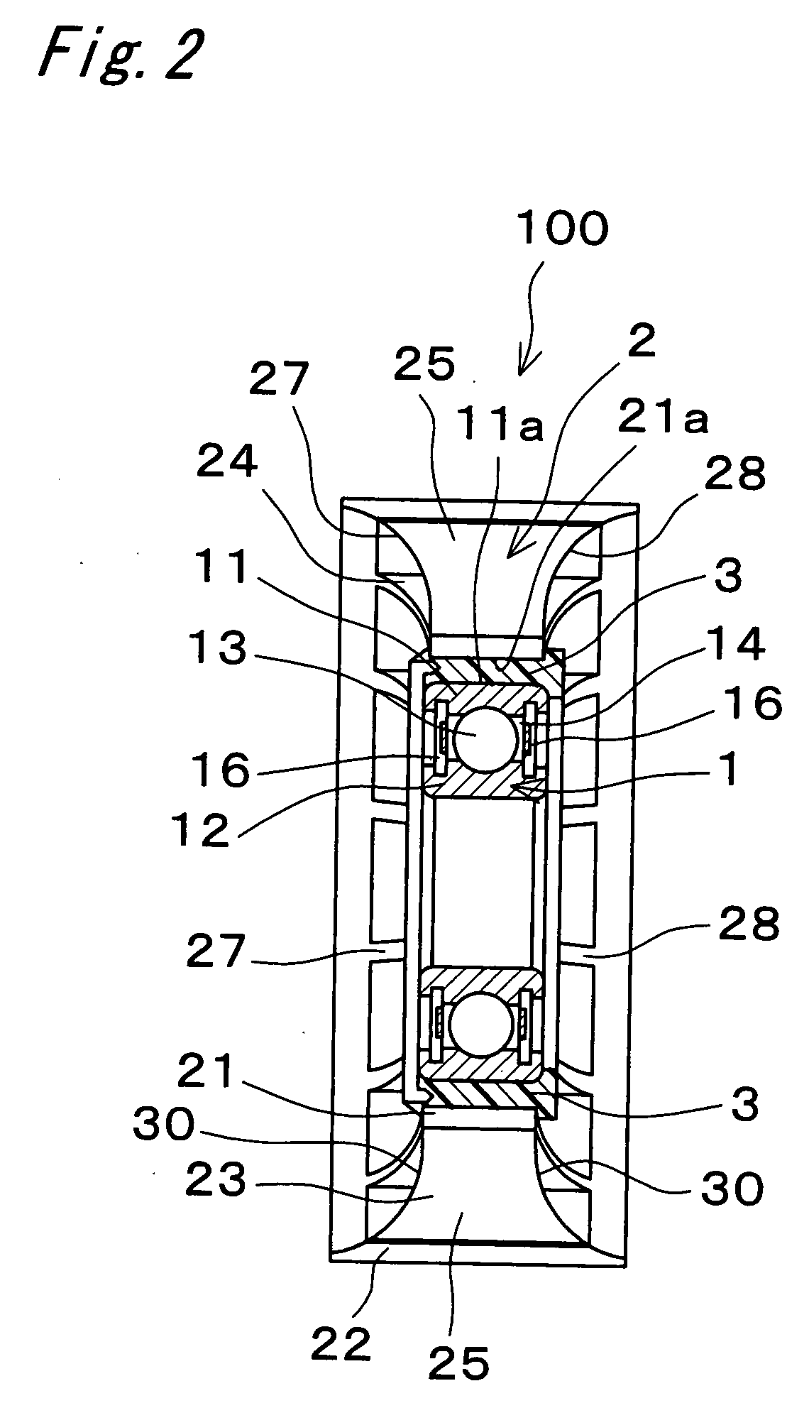
[0024]FIG. 2 is a sectional view taken along the line II-II of FIG. 1.

[0025] As shown in FIG. 2, the pulley assembly 100 includes a ball bearing 1 as an example of a bearing, a light metal pulley 2, and a joint member 3 placed between the ball bearing 1 and the pulley 2.

[0026] The ball bearing 1 has an outer ring 11, an inner ring 12 to be mounted around a shaft not shown in the drawings, and balls 13 placed between the outer ring 11 and the inner ring 12. The outer ring 11, the inner ring 12 and the balls 13 are formed from steel material such as high-carbon chromium bearing steel (SUJ2) or the like. The balls 13 are placed between a raceway groove of the outer ring 11 and a raceway groove of the inner ring 12 circumferentially at specified intervals while being held by an unshown cage. An annular space 14 defined between the outer ring 11 and the inner ring 12 is hermetically closed by seal ...


PUM


Abstract

In a pulley assembly, an annular joint member made of a high polymer material is disposed between an outer ring of a bearing and a light metal pulley. The joint member has a coefficient of thermal expansion larger than that of the pulley. The outer ring has a coefficient of thermal expansion smaller than that of the pulley. The pulley has an annular boss, an annular rim, and a plurality of spokes which have side faces each consisting of a surface parallel to an axial direction of the pulley. Front faces of the spokes are positioned on one identical imaginary surface of revolution, and rear faces of the spokes are also positioned on one identical imaginary surface of revolution.

Description

BACKGROUND OF THE INVENTION [0001] The present invention relates to a pulley assembly and a pulley usable for the pulley assembly. In particular, the invention relates to a pulley assembly and a pulley suitable for use in tensioners or idlers for timing belts of automobile engines, and the like. [0002] Among conventional pulley assemblies to be used in tensioners or idlers for timing belts of automobile engines or the like is one in which with a view to reduction in weight and cost, a resin-made pulley is integrally molded around an outer circumferential surface of a metallic outer ring of a bearing (see JP 2001-200917 A). [0003] However, this conventional pulley assembly has a problem that because of a difference in coefficient of thermal expansion between the material of the outer ring and the material of the pulley, creeps may occur between the outer ring of the bearing and the pulley due to a difference in thermal expansion resulting from temperature increases. [0004] Besides, b...

Claims


Application Information

Patent Timeline
IPC IPC(8): F16H7/20F16H55/36F16H55/40
CPCF16H55/48
Inventor UENO, HIROSHIYANAI, KUNIO
Owner JTEKT CORP
Why Eureka
Try Eureka