Apparatus and methods for delivering fluid and material to a subject

a technology of apparatus and fluid, applied in the direction of infusion needles, other medical devices, infusion syringes, etc., can solve the problems of unfavorable small-volume injection methods, large arrangement that is unwieldy to operate, and lack of mechanisms

Active Publication Date: 2007-10-04
ADERANS RES INST
View PDF47 Cites 99 Cited by
  • Summary
  • Abstract
  • Description
  • Claims
  • Application Information

AI Technical Summary

Benefits of technology

[0012] In another embodiment of the invention, the invention provides a fluid delivery device comprising a housing body, a pinion housing, a pinion, a detachable syringe cartridge, and a trigger portion on the housing body. The housing body has an exterior and an interior with the pinion housing secured on the interior of the housing body. The pinion housing has an aperture designed to receive the pinion. The pinion is in turn secured to the pinion housing so that it can rotate within the pinion receiving aperture. The pinion itself has a front section having gear ridges, a syringe cartridge receiving aperture and a rear section. The syringe cartridge comprises a head portion, a syringe body, a main portion, a plunger and a needle. The head portion of the syringe cartridge engages with a portion of the housing body to secure the syringe cartridge to the housing body. The head portion is attached to the syringe body which has an interior channel. The syringe body is connected to the main body portion of the cartridge. The main body of the cartridge also has an interior channel which is aligned with the interior channel of the syringe body. The interior channel of the main body has a threaded portion. The plunger of the syringe cartridge is received by the interior channels of the syringe body and the main body. The plunger has a plunger tip, a threaded screw section which engages with the threaded portion of the interior channel of the main body in a screw like fashion, and a tail section. The tail section of the plunger is received by the syringe receiving aperture of the pinion and engages with the rear section of the pinion such that when the pinion is turned the syringe plunger is turned and moves forward in the syringe body. The needle of the syringe cartridge is attached to the head portion and is operatively connected to the interior channel of the syringe body. The trigger portion of the device has a tab section which is adapted to engage with a gear ridge of the pinion when depressed, the trigger portion being attached at one end to the pinion housing.

Problems solved by technology

Current methods for injecting small amounts of material are problematic.
There are, however, problems with this current technology.
Firstly, while commercially available micrometer heads allow for the plunger of a syringe to be depressed, they do not contain a mechanism to “pull back” the plunger in order to aspirate discreet amounts of fluid into a syringe.
Secondly, the design of standard micrometer / syringe systems leads to a large arrangement that is unwieldy to operate and often requires two hands to operate, one to hold the syringe steady, the other to operate the micrometer head.
Another problem with injecting small amounts of material such as cells, is the damage that is done to the material when it is injected.
When small amounts of cells are injected, the aspiration of cells into a syringe often causes damage to the morphology of the cells, which can impact their viability when injected into a host.
Furthermore, when only small amounts of material are injected, the removal of the needle injecting the material can often “pull back” some of the material out of the injection site when removed.

Method used


Image

  • Apparatus and methods for delivering fluid and material to a subject
  • Apparatus and methods for delivering fluid and material to a subject
  • Apparatus and methods for delivering fluid and material to a subject

Examples


example 1

Use of the Micrometer Assisted Delivery Device to Deliver a Hair Follicle Cell Suspension to a Subject

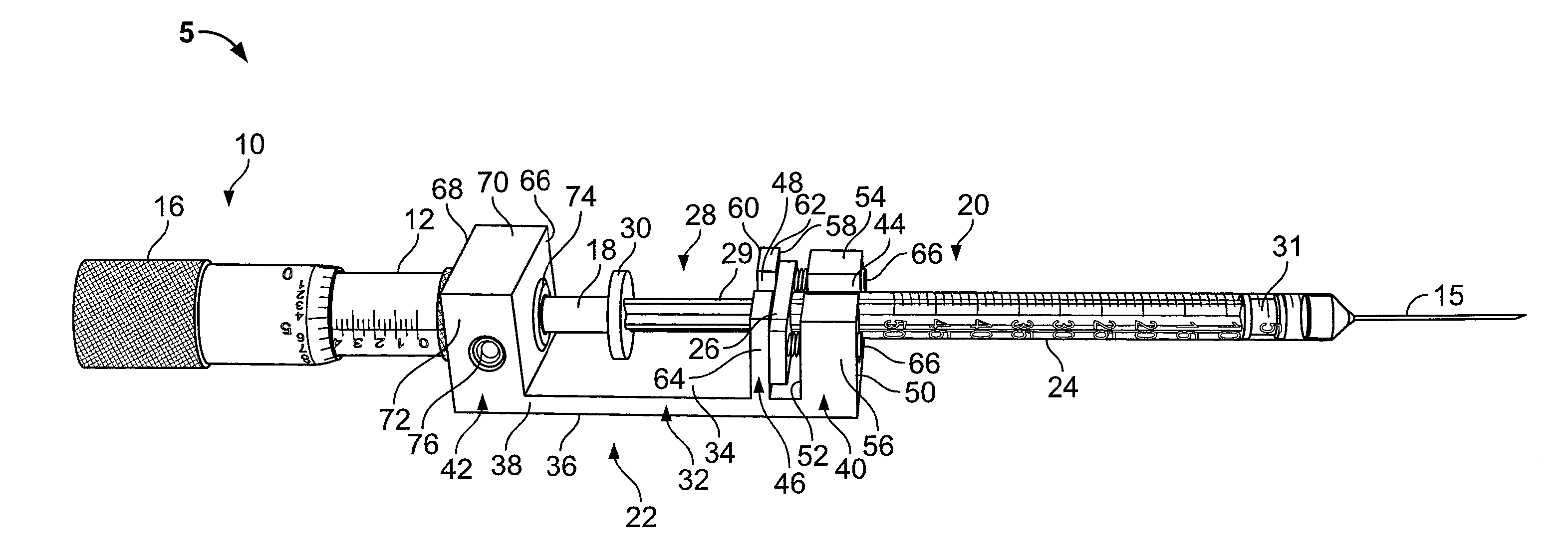
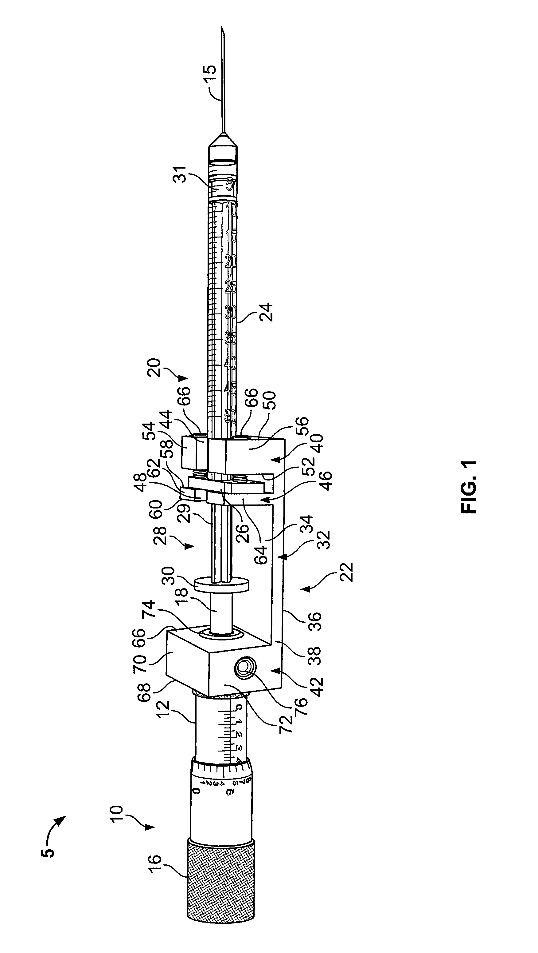
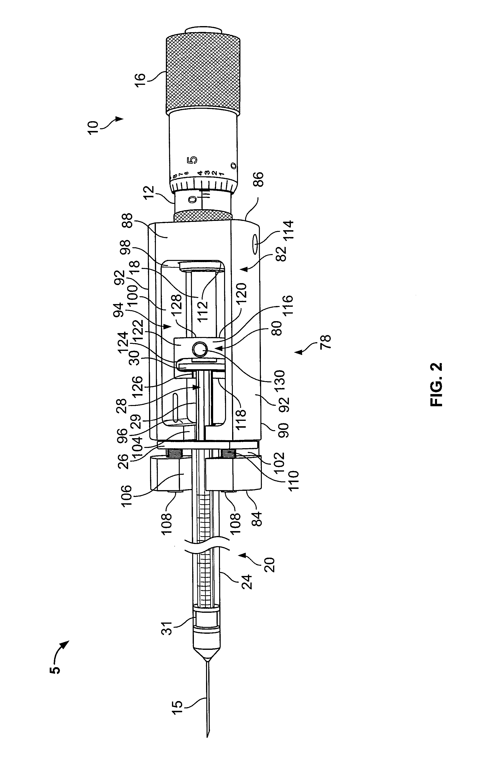
[0080] In this example, the embodiment of the micrometer assisted delivery device used may be any of the embodiments described above or shown in FIGS. 1-8.

[0081] Preparing the Micrometer Assisted Delivery Device

[0082] A ½ inch long 0.5 cc insulin needle is placed in the micrometer assisted delivery device holder and secured. The user should verify that the needle bevel is facing upward between the 10 o'clock to 2 o'clock positions. The user should then aspirate the required amount of solution into the micrometer assisted delivery device by turning the micrometer adjustment thimble clockwise. To push the syringe plunger forward, the user turns the micrometer adjustment thimble counterclockwise. If an air bubble is present, the user should remove by tapping the syringe body and expelling the air bubble out vertically, continue until a small volume of solution appears on the tip of ...

example 2

Use of Fluid Delivery Device to Deliver a Hair Follicle Cell Suspension to a Subject

[0088] In this example, the embodiment of the fluid delivery device used may be any of the embodiments described above or shown in FIGS. 9-15.

[0089] Preparing the Fluid Delivery Device

[0090] The needle of the syringe cartridge is placed within a cell suspension. The plunger of the syringe cartridge is rotated to pull back the syringe head and draw the cell suspension into the syringe cartridge. The syringe cartridge is placed within the housing body of the fluid delivery device. The trigger is depressed down and up until the cell suspension is visible on the needle tip.

[0091] Needle Insertion

[0092] The user should slide the needle superficially into the skin keeping the needle bevel side up and needle parallel to the surface of the skin. Tension in the skin may be increased by pinching the skin, spreading the skin between the user's fingers or pushing forward on the skin surface. The increased s...

example 3

Use of the Cellular Material Delivery Device

[0096] In this example, the embodiment of the cellular material device used may be any of the embodiments described above or shown in FIGS. 16-20.

[0097] Trichogenic epithelial and dermal cells were aggregated and placed in a suspension on the back of a nu / nu mouse. Using the cellular material device, the skin of the mouse was pierced and the device was inserted into the mouse, the annular grooves picking up the suspension from the surface and conveying the material beneath the surface of the skin of the mouse. The injections were repeated by 20× penetrations of the skin through the cell suspension drop. After 10 days of incubation hair follicle formation was seen within the dermis. This experiment was repeated, with the same success, on two further occasions using the same needle configuration.


PUM


Abstract

The present invention provides fluid and material delivery methods and devices for practicing the methods. The invention provides a method of delivering cellular material comprising injecting the cellular material into a subject such that the injected cells retain their inherent morphologic characteristics upon injection. The method comprises the steps of aspirating the cellular material into a fluid delivery device which incorporates a syringe arrangement. The cellular material is aspirated into the main body of the syringe until the desired amount of a material has filled the syringe body. The needle of the fluid delivery device is then inserted into the skin of a subject at an angle about parallel to the skin until a desired depth has been reached. The cellular material is then injected in the subject until the desired volume of material has been injected. The needle of the device is then rotated approximately 45 to 90 degrees and the needle is removed from the injection site.

Description

CROSS-REFERENCE TO RELATED APPLICATIONS [0001] This application claims the benefit of priority of U.S. Provisional Application No. 60 / 771,915, filed Feb. 9, 2006, U.S. Provisional Application No. 60 / 791,489, filed Apr. 12, 2006, and U.S. Provisional Patent Application No. 60 / 803,248 filed May 26, 2006. These applications are incorporated by reference in their entirety.BACKGROUND OF THE INVENTION [0002] Current methods for injecting small amounts of material are problematic. One solution has been to use micrometer heads along with a syringe to deliver precise small amounts of fluid from a syringe. There are, however, problems with this current technology. Firstly, while commercially available micrometer heads allow for the plunger of a syringe to be depressed, they do not contain a mechanism to “pull back” the plunger in order to aspirate discreet amounts of fluid into a syringe. Secondly, the design of standard micrometer / syringe systems leads to a large arrangement that is unwieldy...

Claims


Application Information

Patent Timeline
Patent Type & Authority Applications(United States)
IPC IPC(8): A61M5/00A61M31/00
CPCA61M5/3148A61M5/31551A61M5/31573A61M5/31586A61M2005/342A61M2005/2411A61M2005/2414A61M2005/341A61M37/00
Inventor PRUITT, TERRELLCOCHRAN, STEPHEN A.MARSHALL, BRYANSU, YANDONGSTENN, KURT STRICKERWASHENIK, KENNETH JUSTINDEPIANO, JOHNPROKOP, GARY F.RATHGEBER, MARTIN
Owner ADERANS RES INST
Why Eureka
Try Eureka