Bone-Evacuating and Valve-Exiting Resector and Method of Using Same

Inactive Publication Date: 2007-10-04
WASHINGTON UNIV IN SAINT LOUIS
View PDF3 Cites 12 Cited by
  • Summary
  • Abstract
  • Description
  • Claims
  • Application Information

AI Technical Summary

Benefits of technology

[0004] To eliminate the above noted shortcomings of the prior art device and its method of use, the inventors have succeeded in developing a pneumatically powered bone resector and collection device which represents a significant improvement over the prior art device. The new invention may remain in the surgical opening while multiple resections are made, power the cutting operation so that the surgeon need only place the tool and not be required to squeeze or exert hand pressure to achieve the cutting, and automaticall

Problems solved by technology

Furthermore, it is also the case that prior art devices require a process of continual insertion and removal of the bone resector which is not only a time consuming and cumbersome process but also provides opportunity for infection du

Method used


Image

  • Bone-Evacuating and Valve-Exiting Resector and Method of Using Same
  • Bone-Evacuating and Valve-Exiting Resector and Method of Using Same
  • Bone-Evacuating and Valve-Exiting Resector and Method of Using Same

Examples


Embodiment Construction

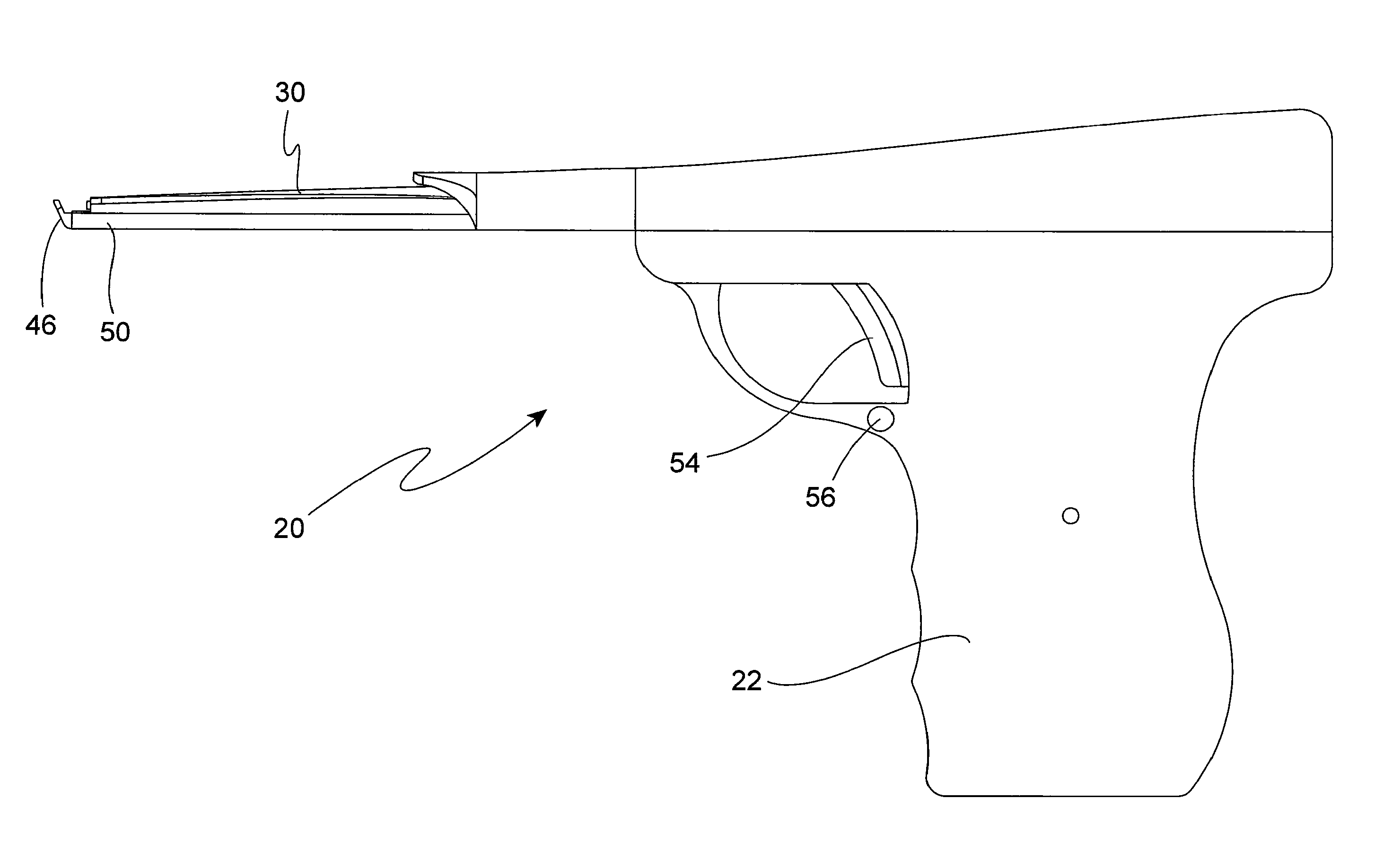
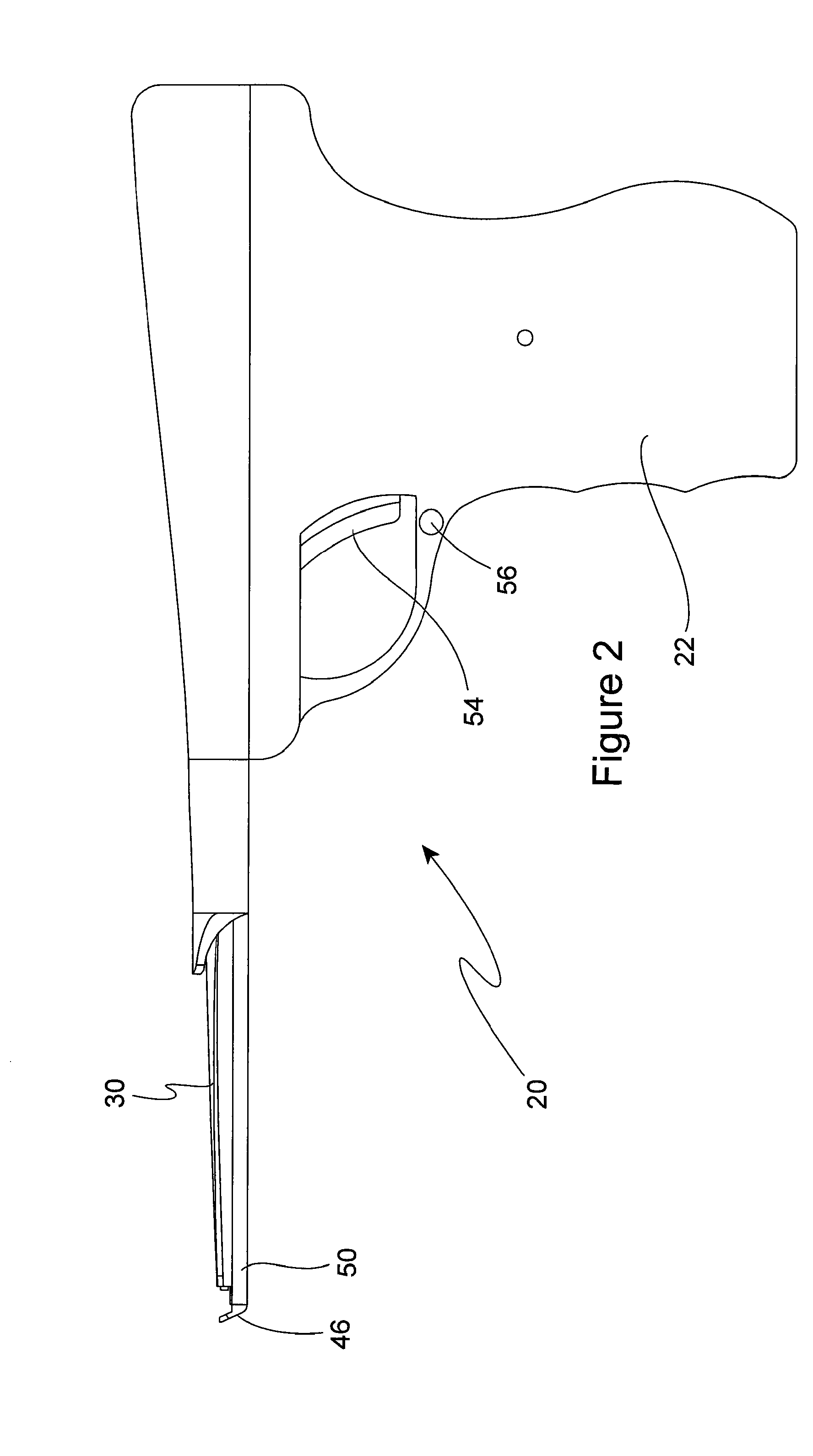
[0011] The bone resector 20 of the present invention comprises a hand held carrier 22 preferably shaped in the form of a handgun for ease and familiarity of use by a surgeon. Inside the carrier 22 is mounted a dual action pneumatic cylinder 24 having its piston 26 connected to a mechanical linkage 28 for driving and retracting a cutting arm 30. The mechanical linkage 28 comprises a sliding yoke 32 attached to the piston 26 with a hole therethrough which mounts the sliding yoke 32 to a guide post 34 to guide it as the pneumatic cylinder is actuated. The yoke 32 has two yoke arms 36 which are bridged by a pin 38 extending through a slot 40 in a second guide arm 42 so that as the cylinder is actuated, the piston extends to drive the yoke along the first guide post and move the pin through the second guide arm, thereby pushing the second guide arm forward to drive it forwardly of the carrier 22. The cutting arm 30 is slidingly mounted to the top of the carrier 22 and is connected to the...


PUM


Abstract

A pneumatically powered bone resector has a moveable cutting arm and a stationary foot against which the cutting arm homes to cut bone positioned therebetween, the cutting arm being hollow for receiving resected bone with a mechanical/pneumatic linkage connected to the cutting arm for driving the cutting arm and blowing the resected bone through the cutting arm and into a receiving bin, an electronically controlled pneumatic power supply for powering the linkage upon operation of a trigger, the trigger being operated by a surgeon.

Description

CROSS-REFERENCE AND PRIORITY CLAIM TO RELATED APPLICATIONS [0001] This application claims priority to U.S. provisional patent application Ser. No. 60 / 779,400, entitled “Bone-Evacuating and Valve-Exiting Resector and Method of Using Same”, filed Feb. 24, 2006.BACKGROUND AND SUMMARY OF THE INVENTION [0002] Surgical tools for resecting bone are well known in the prior art. These tools are used to reach inside an incision and resect or “chip” away the bone from a patient for any one of several reasons. This process generally takes place as the patient is under some form of anesthesia which dictates that the speed of the operation be given some urgency. Furthermore, it is also the case that prior art devices require a process of continual insertion and removal of the bone resector which is not only a time consuming and cumbersome process but also provides opportunity for infection due to the possible introduction of foreign materials into the incision. For these reasons the prior art dev...

Claims


Application Information

Patent Timeline
IPC IPC(8): A61B17/00
CPCA61B2017/00544A61B17/1611
Inventor COHEN, TAYLOR S.DACEY, RALPH G. JR.FERBER, AARONGENIN, GUY M.JANSEN, DANIELLEUTHARDT, ERIC C.NATHAN, ADAM C.SABET, ARASH
Owner WASHINGTON UNIV IN SAINT LOUIS
Why Eureka
Try Eureka