
Detecting computer system simulation errors

a computer system and simulation error technology, applied in the field of detecting computer system simulation errors, can solve the problems of limited bandwidth for communication between computer systems, hardware limitations of each computer system within the network environment, and communication cannot take pla

Inactive Publication Date: 2007-10-04
MICROSOFT TECH LICENSING LLC
View PDF0 Cites 13 Cited by
  • Summary
  • Abstract
  • Description
  • Claims
  • Application Information

AI Technical Summary

Benefits of technology

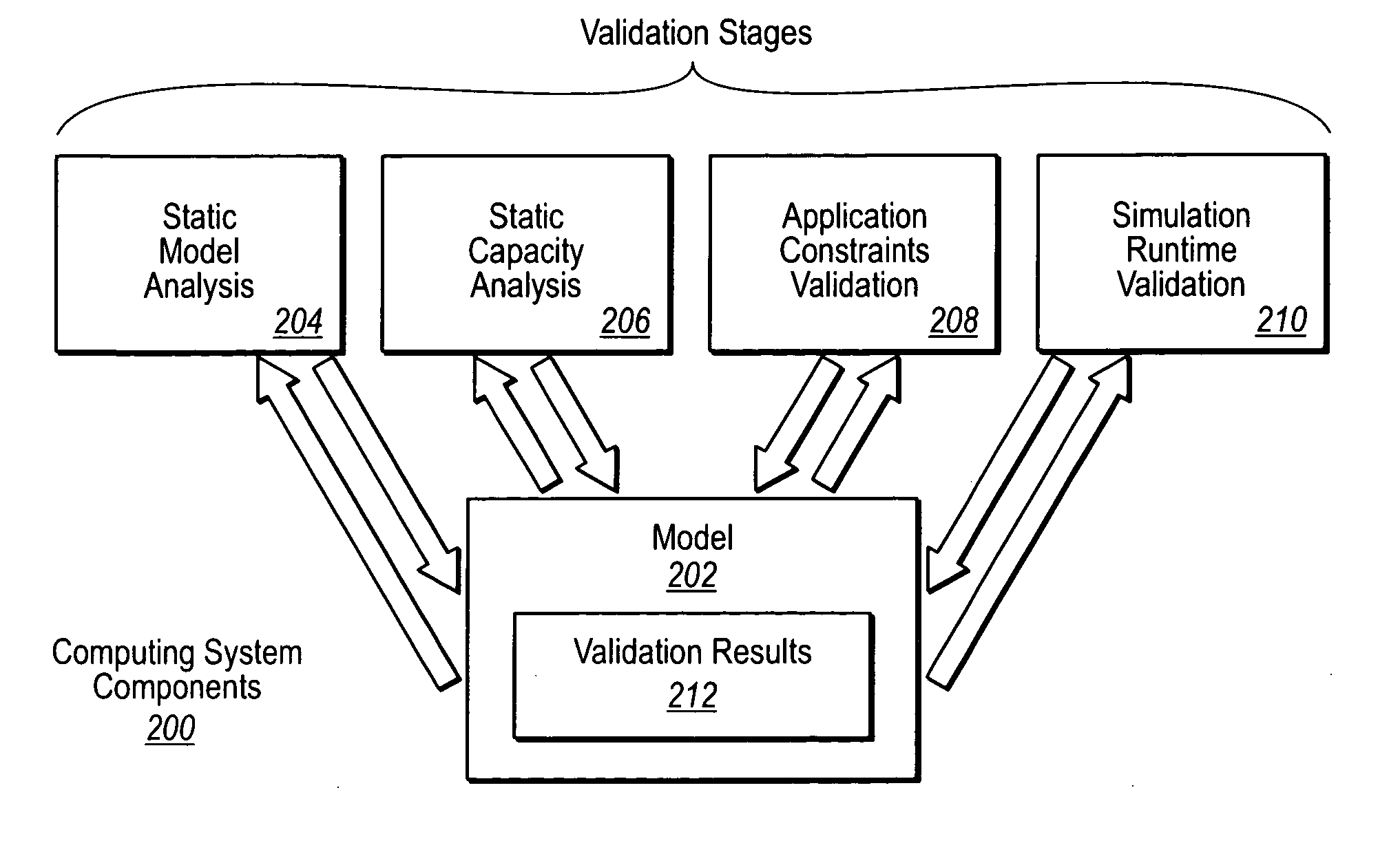
[0008] One embodiment described herein includes computer readable media implemented in a computing environment. The computing environment includes a performance scenario of a system. The performance scenario includes device models defining device behavior and/or capacity. The performance scenario further includes interconnections between one or more device models. The computer readable media includes computer executable instructions configured to perform a static model analysis of the system. The static model analysis analyzes at least one o

Problems solved by technology

Each of the computer systems within a network environment has certain hardware limitations.
For example, network cards that are used to communicate between computer systems have a limited amount of bandwidth meaning that communications can only take place at or below a predetermined threshold rate.
Hard disk drives are limited in the amount of data that can be stored on the disk drive as well as limited in the speed at which the hard disk drives can store the data.
When simulating complex computing systems, a significant amount of effort is required to build the model and to ensure that the model includes appropriate interconnections between model devices.
Additionally, because of the complexities of some simulations, it may be likely that a significant number of errors may be generated during the simulation.
Corrections are then made and the simulation run again, which may produce the same or other errors.

Method used


Image

  • Detecting computer system simulation errors
  • Detecting computer system simulation errors
  • Detecting computer system simulation errors

Examples


Embodiment Construction

[0020] Embodiments herein may comprise a special purpose or general-purpose computer including various computer hardware, as discussed in greater detail below.

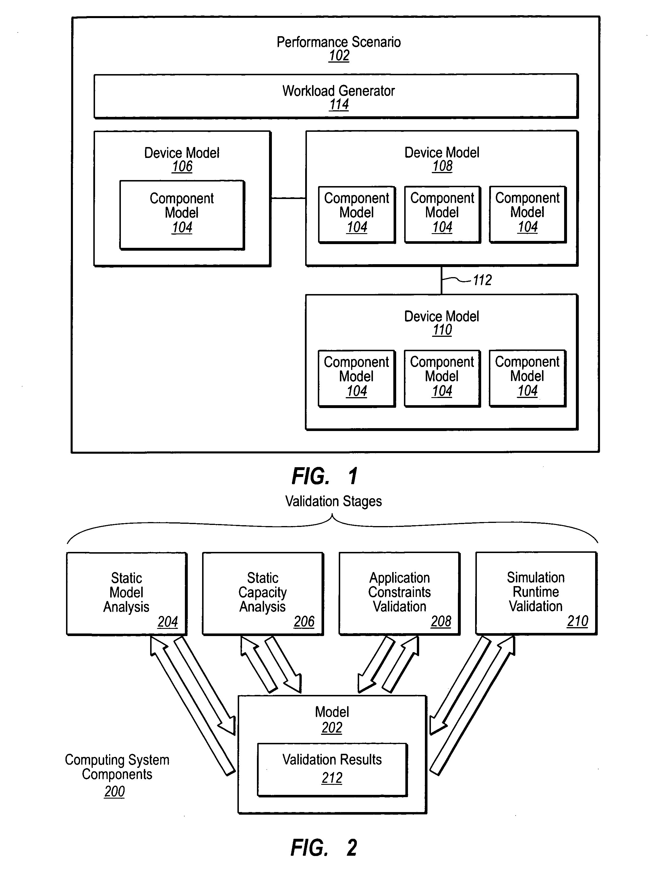
[0021] In one embodiment, a simulation is performed in stages. For example, the simulation may include a static model analysis stage, a static capacity analysis stage, and application constraints validation stage, and a runtime validation stage.

[0022] Referring now to FIG. 1, a performance scenario 102 is illustrated. The performance scenario 102 may include a model of a computing system including device models 104, 106, 108, 110. As illustrated, device models may be connected in a fashion to simulate the computing system. The performance scenario 102 may specify device models are interconnected with one another. For example, the performance scenario 102 may specify servers interconnected with clients. For example, the device model 108 may represent a server model where as the model 110 may represent a client model. An inter...


PUM


Abstract

Validating simulation models. A computing environment includes a performance scenario of a system. The performance scenario includes device models defining device behavior and / or capacity. The performance scenario further includes interconnections between one or more device models. A static model analysis of the system is performed. The static model analysis analyzes at least one of configuration of device models defined by the performance scenario or interconnection of device models defined by the performance scenario. A static capacity analysis to analyze device model limitations as they relate to statically defined performance scenario characteristics is performed. An application constraints validation can be performed. This includes comparing the performance scenario to software deployment best practices and rules related to models similar to the performance scenario. A simulation runtime validation may also be performed to evaluate dynamic device usage and latencies to simulate the system.

Description

BACKGROUND Background and Relevant Art [0001] Computers and computing systems have affected nearly every aspect of modern living. Computers are generally involved in work, recreation, healthcare, transportation, entertainment, household management, etc. The functionality of computers has also been enhanced by their ability to be interconnected through various network connections. [0002] Computer systems can be interconnected in large network configurations so as to provide additional functionality. For example, one typical network configuration is a configuration of computer systems interconnected to perform e-mail functionality. In one particular example, an e-mail server acts as a central location where users can send and retrieve emails. For example, a user may send an e-mail to the e-mail server with instructions to the e-mail server to deliver the message to another user connected to the e-mail server. Users can also connect to the e-mail server to retrieve messages that have b...

Claims


Application Information

Patent Timeline
IPC IPC(8): G06F17/10G06F17/50
CPCG06F17/5009G06F30/20
Inventor PAPAEFSTATHIOU, EFSTATHIOSOSLAKE, JOHN M.HARDWICK, JONATHAN C.DOURNOV, PAVEL A.NAIK, ROHIT R.
Owner MICROSOFT TECH LICENSING LLC
Learn More