Spacecraft thruster

a thruster and spacecraft technology, applied in the field of spacecraft thrusters, can solve the problems of reducing the service life of the thruster, affecting the stability of the thruster, and the need for a very high voltage between the accelerating grid,

Inactive Publication Date: 2007-10-11
ELWING LLC
View PDF17 Cites 17 Cited by
  • Summary
  • Abstract
  • Description
  • Claims
  • Application Information

AI Technical Summary

Problems solved by technology

One of the problems of this type of device is the need for a very high voltage between the accelerating grids.
Another problem is the erosion of the grids due to the impact of ions.
Last, neutralizers and grids are generally very sensitive devices.
Like in ionic grid thruster, there is a problem of erosion and the presence of neutralizer makes the thruster prone to failures.

Method used


Image

  • Spacecraft thruster
  • Spacecraft thruster
  • Spacecraft thruster

Examples


first embodiment

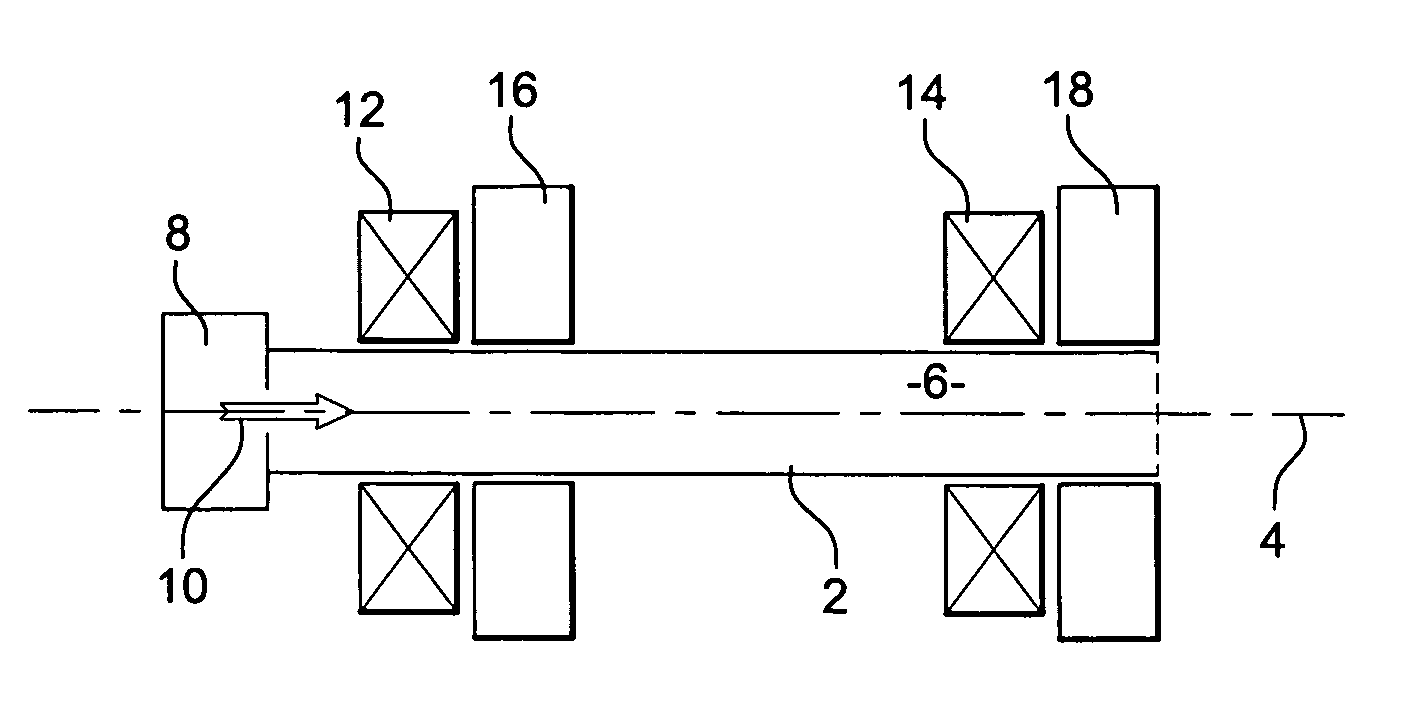
[0063]FIG. 1 is a schematic view in cross-section of a thruster according to the invention. The thruster of FIG. 1 relies on electron cyclotron resonance for producing a plasma, and on magnetized ponderomotive force for accelerating this plasma for producing thrust. The ponderomotive force is the force exerted on a plasma due to a gradient in the density of a high frequency electromagnetic field. This force is discussed in H. Motz and C. J. H. Watson (1967), Advances in electronics and electron physics 23, pp.153-302. In the absence of a magnetic field, this force may be expressed as F=q24⁢m⁢ ⁢ω2⁢∇E2

for one particule F=-ωp22⁢ω2⁢∇ɛ0⁢E22

for the plasma with ωp2=n⁢ ⁢ⅇ2me⁢ɛ0

In presence of a non-uniform magnetic field this force can be expressed as: F=q24⁢m⁢ ⁢ω⁢(∇E2(ω-Ωc)-E2(ω-Ωc)2⁢∇Ωc)-μ⁢ ⁢∇B

[0064] The device of FIG. 1 comprises a tube 2. The tube has a longitudinal axis 4 which defines an axis of thrust; indeed, the thrust produced by the thruster is directed along this axis—alth...

second embodiment

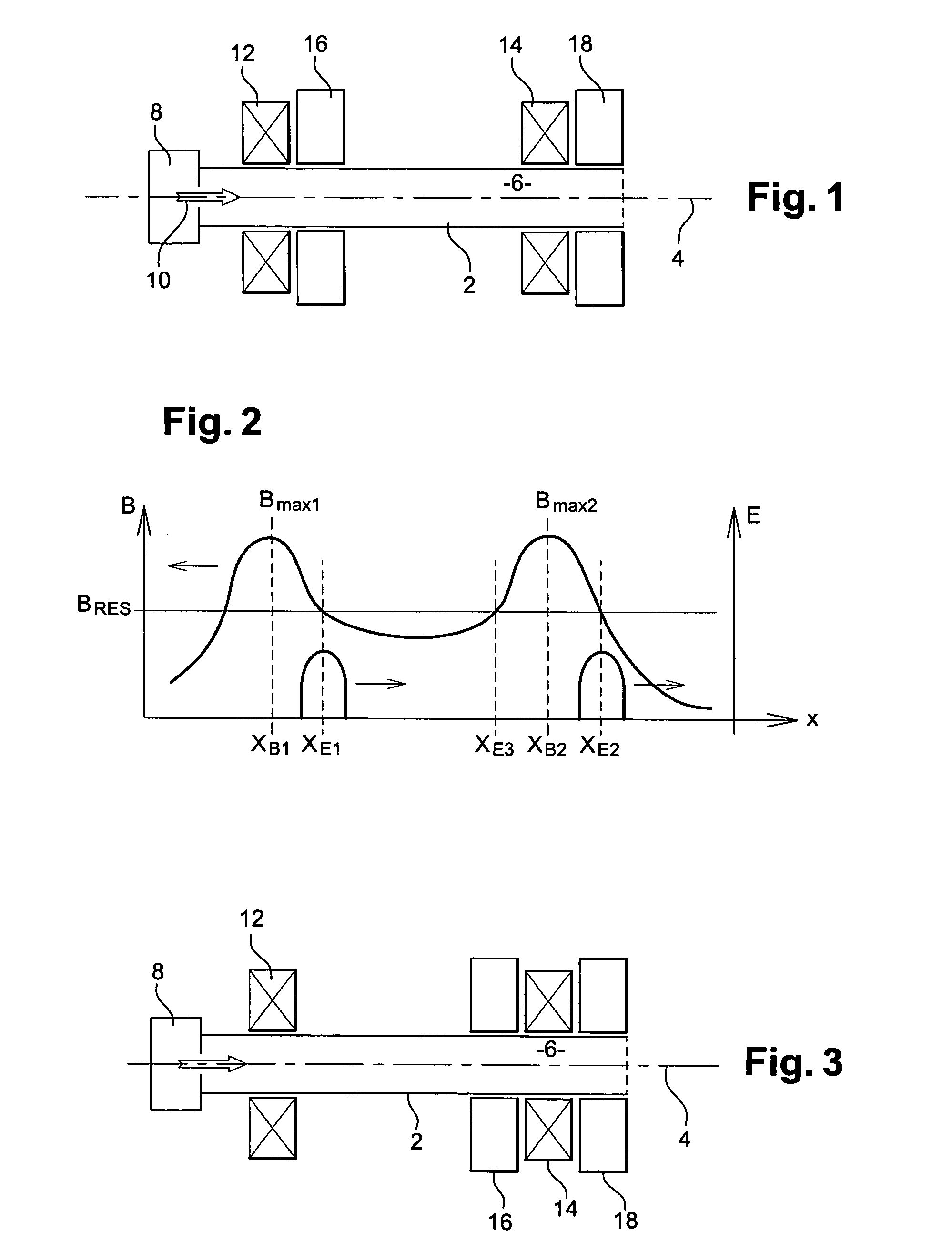
[0089]FIG. 3 is a schematic view in cross-section of a thruster in the invention. The example of FIG. 3 differs from the example of FIG. 1 in the position of the first resonant cavity 16, which is located near to the coil 14 producing the second maximum of the magnetic field. Specifically, the resonant cavity is located along the axis at a coordinate x=xE3=205 mm. As represented on FIG. 2, this position is selected so that the value of the magnetic field at this position is identical to the value of the magnetic field at the position xE1. This makes it possible to use the same resonant cavity, without having to adapt the value of the frequency of the electromagnetic field. One could also use two resonant cavities at the coordinates xE1 and xE2 for generating the electromagnetic field within the ionization volume. Again, this may improve the proportion of gas ionized within the ionization volume. Having the cavity on the right-hand side may diminish erosion.

third embodiment

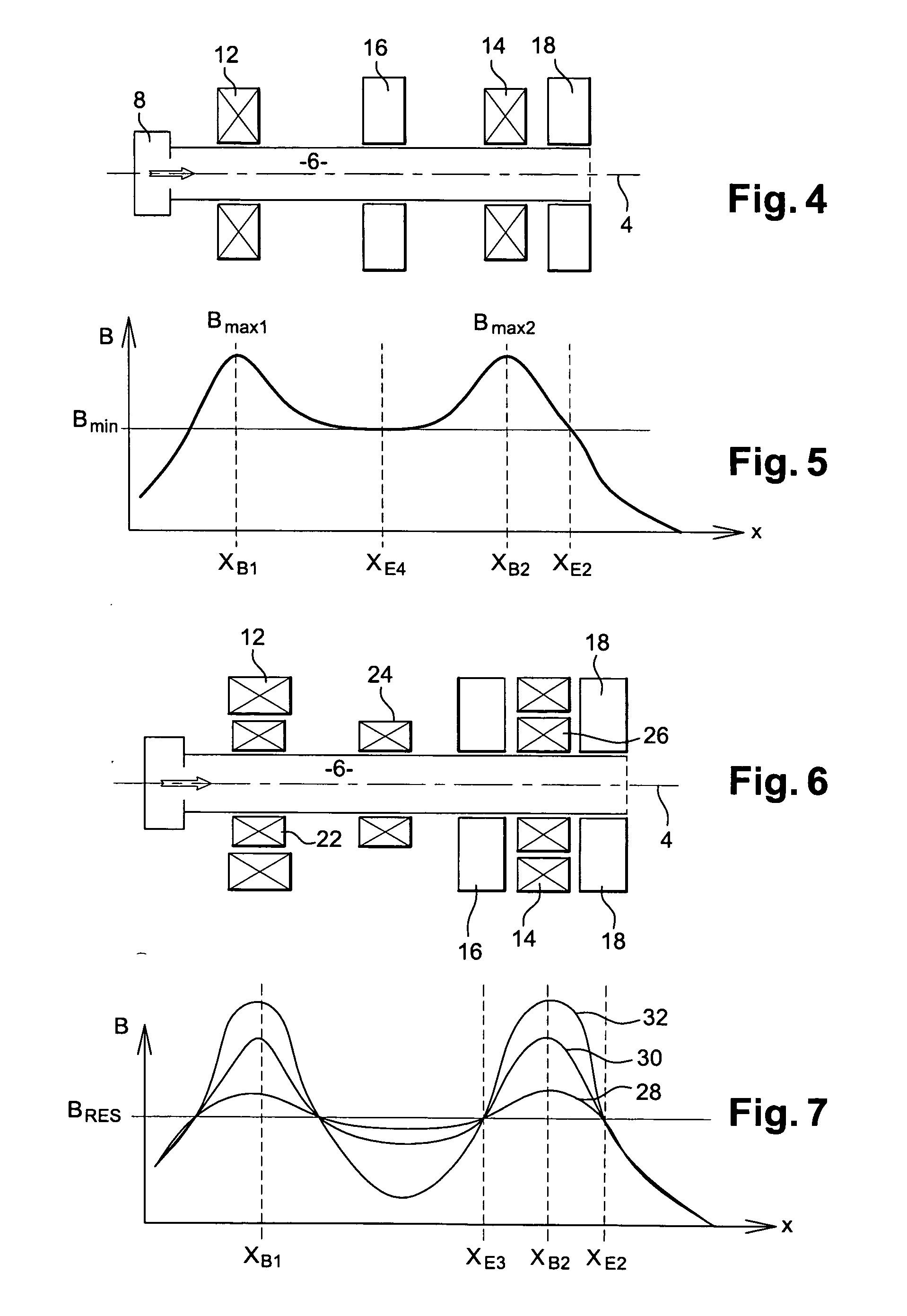
[0090]FIG. 4 is a schematic view in cross a thruster in the invention; FIG. 5 is a diagram of the intensity of magnetic and electromagnetic fields along the axis of the thruster of FIG. 4. The thruster of FIG. 4 is similar to the one of FIG. 1. However, the first resonant cavity 16 is located substantially in the middle of the coils 12 and 14. FIG. 5 is similar to FIG. 2, but shows the intensities of the magnetic field in the embodiment of FIG. 4. It shows that the first resonant cavity is located substantially at the coordinate xE4, which corresponds to the minimum value Bmin of the magnetic field. The frequency of the electromagnetic field is selected to be e.Bmin / 2πm. The second resonant cavity is located at a position where the magnetic field has the same value. Again, this makes it possible to use the same microwave generator for driving both cavities. The advantage of the embodiment of FIGS. 4 and 5 is that the value of the magnetic field is substantially identical over the vo...


PUM


Abstract

A thruster has a chamber defined within a tube. The tube has a longitudinal axis which defines an axis of thrust; an injector injects ionizable gas within the tube, at one end of the chamber. A magnetic field generator with two coils generates a magnetic field parallel to the axis; the magnetic field has two maxima along the axis; an electromagnetic field generator has a first resonant cavity between the two coils generating a microwave ionizing field at the electron cyclotron resonance in the chamber, between the two maxima of the magnetic field. The electromagnetic field generator has a second resonant cavity on the other side of the second coil. The second resonant cavity generates a ponderomotive accelerating field accelerating the ionized gas. The thruster ionizes the gas by electron cyclotron resonance, and subsequently accelerates both electrons and ions by the magnetized ponderomotive force.

Description

CROSS REFERENCE TO RELATED APPLICATIONS [0001] This application is a continuation of PCT / US2004 / 008054, filed Mar. 17, 2004, which claims priority to European Patent Application No. EP 03290712.3, filed Mar. 20, 2003, both of which are incorporated by reference herein.BACKGROUND AND SUMMARY OF THE INVENTION [0002] The invention relates to the field of thrusters. Thrusters are used for propelling spacecrafts, with a typical exhaust velocity ranging from 2 km / s to more than 50 km / s, and density of thrust below or around 1 N / m2. In the absence of any material on which the thruster could push or lean, thrusters rely on the ejection of part of the mass of the spacecraft. The ejection speed is a key factor for assessing the efficiency of a thruster, and should typically be maximized. [0003] Various solutions were proposed for spatial thrusters. U.S. Pat. No. 5,241,244 discloses a so-called ionic grid thruster. In this device, the propelling gas is first ionized, and the resulting ions are...

Claims


Application Information

Patent Timeline
Patent Type & Authority Applications(United States)
IPC IPC(8): F03H1/00
CPCF03H1/0081
Inventor EMSELLEM, GREGORY
Owner ELWING LLC
Why Eureka
Try Eureka