Countermeasures radiation source for missile decoys

a radiation source and missile technology, applied in the field of decoys, can solve the problems of limited value as a decoy and catalytic burning

Inactive Publication Date: 2007-10-11
VAN LAAR KURT DANIEL +1
View PDF8 Cites 11 Cited by
  • Summary
  • Abstract
  • Description
  • Claims
  • Application Information

AI Technical Summary

Benefits of technology

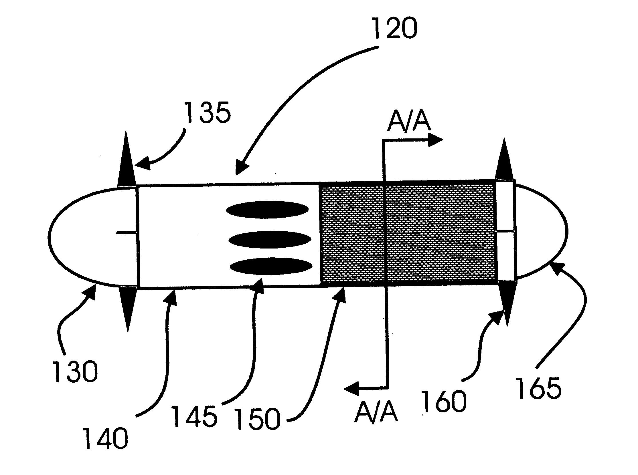
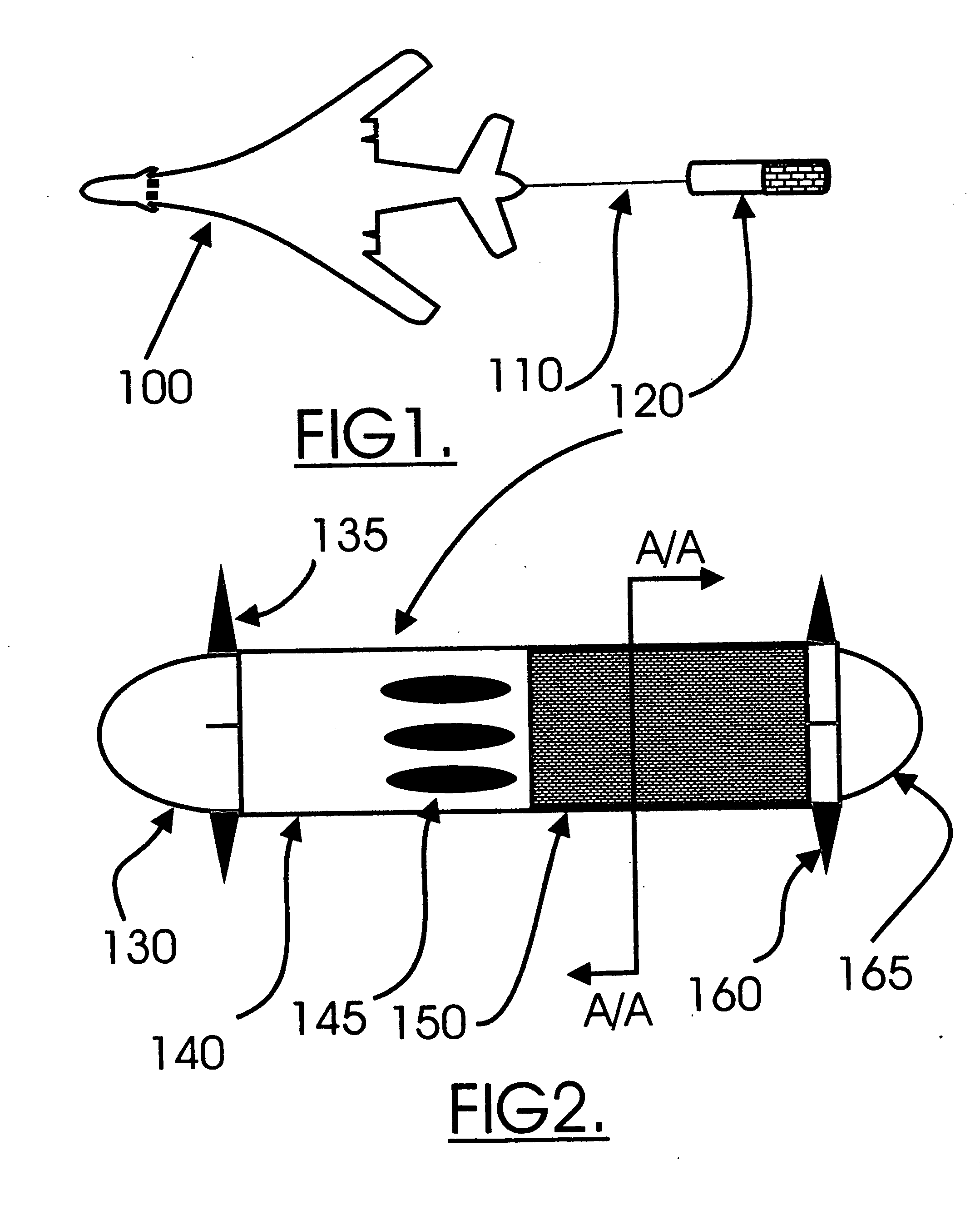
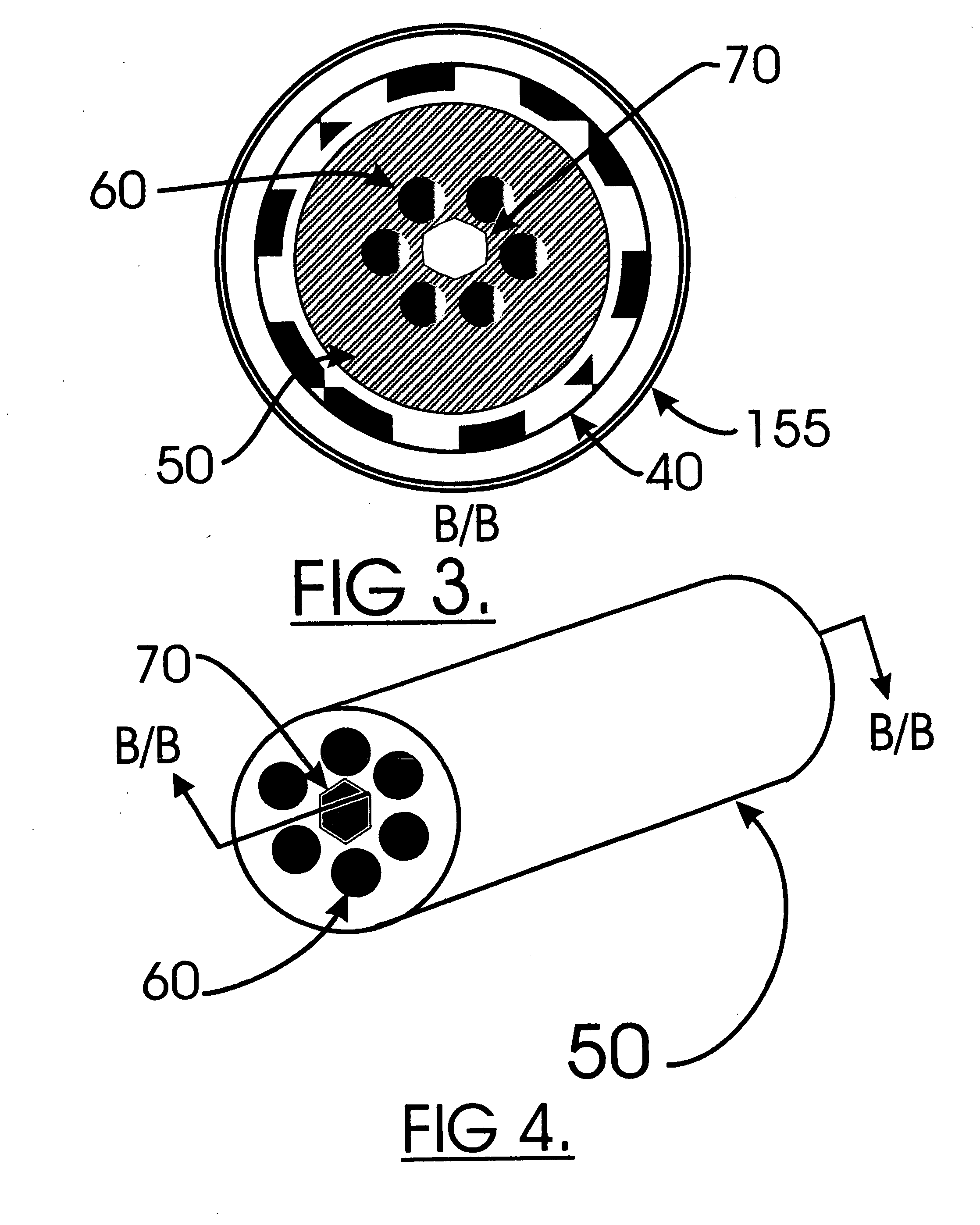
[0013] U.S. Pat. No. 6,352,031 Barbaccia. “Radiative countermeasures method”. Barbaccia uses a towed decoy and expels discreet clouds of gelled fuel and igniting the cloud. This differs in that in the decoy methodology being presented the radiation is continuous with the chopping frequency being created by the chopping cylinder[40] this presents more believable signat...

Problems solved by technology

Catalyzed burning takes place on the ...

Method used


Image

  • Countermeasures radiation source for missile decoys
  • Countermeasures radiation source for missile decoys
  • Countermeasures radiation source for missile decoys

Examples


Embodiment Construction

[0026] When a decoy is deployed the control surfaces processor deploys the fore and aft control surfaces and maneuvers the decoy though a programmed set of maneuvers. At the same time the burner control microcomputer deploys the air inlet ducts, spins up the chopper assembly, pressurizes the fuel, opens the fuel control and ignites the fuel. The burning fuel vents through the reticulated ceramic walls causing the ceramic and it's embedded catalysts to heat up to the working temperature where the catalysts radiate specific bands of energy primarily in the UV and IR bands. The spinning chopper assembly chops the radiation to make it appear as a jet aircraft turbine.

[0027] Fuel flow, airflow and chopper speed are all managed by the microcomputer so as to simulate the specific aircrafts spectral signature with the overall output being higher than the target aircraft but below the deception discrimination thresholds of Stinger-2 / 3, Soviet and Chinese SA-14 and subsequent MANPADS counter...


PUM


Abstract

A missile decoy countermeasures radiation source that provides a controlled radiation source that emulates jet aircraft engines, wherein the radiation generating elements utilizes specific catalysts, dopings and fuel additives burned within a reticulated ceramic matrix. Further a variable speed multi-element rotating blade structure is incorporated to provide the chopping of the radiation. The reticulated ceramic burner is doped such that radiation spectral lines are highest in those bands that are of interest to anti-aircraft missile seekers. The outermost surface of the decoy body is fabricated from reticulated ceramics that are transparent to the select lines of radiant energy, is breathable and a smooth, providing an aerodynamic surface for fast moving aircraft. Further the injection of specific catalysts, dopings and fuel additives provide for real-time spectral management and the injection of oxidizers allows for high altitude operations.

Description

STATEMENT OF FEDERALLY SPONSORED RESEARCH [0001] There is NO Federal Sponsorship. FIELD OF INVENTION [0002] This invention relates to Decoys more specifically Missile Decoys and a Radiating Device being applied integral to the missile decoy body increasing the infrared [IR] and Ultraviolet [UV] signatures of the decoy. BENEFITS OF INVENTION [0003] This radiation source provides a much more attractive set of IR and UV signatures to a Missile Seeker. The device uses of a reticulated ceramic burner doped with the correct rare earth oxides to provide a spectrally matched set of specific signatures to an aircraft type. Active chopping of radiation further deceives the incoming missiles guidance by causing the radiation to appear as if turbine blades are chopping the radiation. The decoy can last from seconds to hours depending on the mission and the availability of fuel. BACKGROUND OF THE INVENTION [0004] Currently most known missile decoys use pyrotechnics to create their IR signatures....

Claims


Application Information

Patent Timeline
IPC IPC(8): B65D3/00F42B4/26
CPCF41J9/10F41J2/00
Inventor VAN LAAR, KURT DANIELBENSON, CHUCK
Owner VAN LAAR KURT DANIEL
Why Eureka
Try Eureka