
Photovoltaic floatation device

a technology of photovoltaic cells and floating devices, which is applied in the direction of special-purpose vessels, energy supply, lighting and heating apparatus, etc., can solve the problems of large surface area of cells exposed to sunlight, large space requirements of photovoltaic cells used to generate electricity, and special effects

Inactive Publication Date: 2007-10-11
SOLAR INTEGRATED TECH
View PDF9 Cites 65 Cited by
  • Summary
  • Abstract
  • Description
  • Claims
  • Application Information

AI Technical Summary

Benefits of technology

[0010] In another embodiment, a system for generating electricity comprises one or more photovoltaic floatation devices that are mechanically connected with one or more fasteners. The system further comprises one or more photovoltaic floatation devices electrically connected to one or more combiner boxes. The one or more combiner boxes are electrically connected to one or more combiner-combiner boxes. The system further comprises one or more inverters, wherein the one or more combiner-combiner boxes are electrically connected to the one or more inverters.

Problems solved by technology

However, one drawback of solar energy is that the photovoltaic cells used to generate the electricity require a large amount of space so that a large surface area of cells can be exposed to sunlight.
This drawback is especially evident in areas where land is scarce and is needed for other applications.
In these areas, land is far too valuable to commit to energy production.
Thus, users in such areas are forced to purchase electricity from a power company or utilize expensive alternatives such as generators.
However, the known art easily collects dirt and water on the top surface.
Moreover, in the known art, electrical wires that carry current between photovoltaic cells are completely exposed to the outside elements and can be easily damaged from strong winds and rocky tides.

Method used


Image

  • Photovoltaic floatation device
  • Photovoltaic floatation device
  • Photovoltaic floatation device

Examples


Embodiment Construction

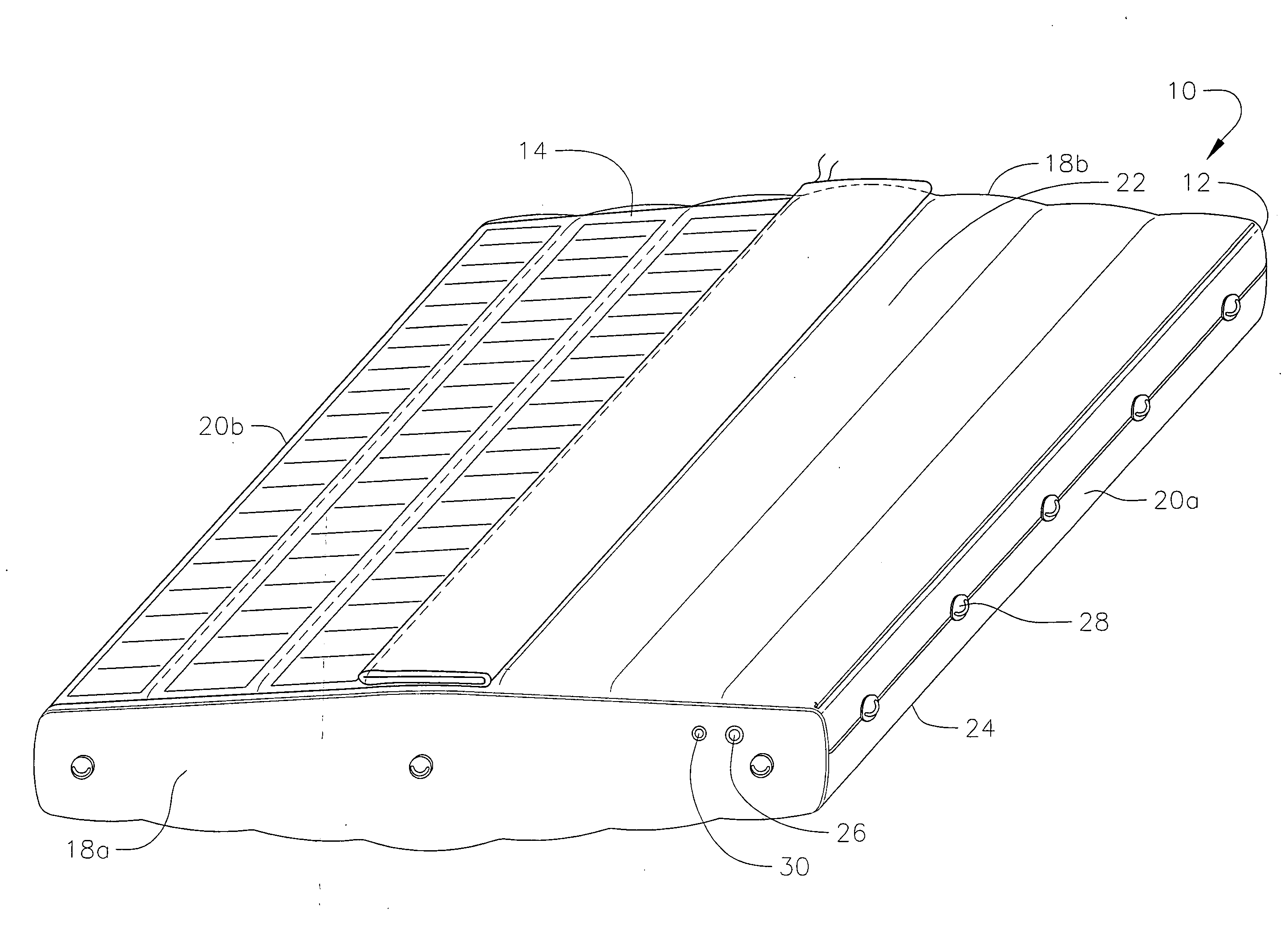
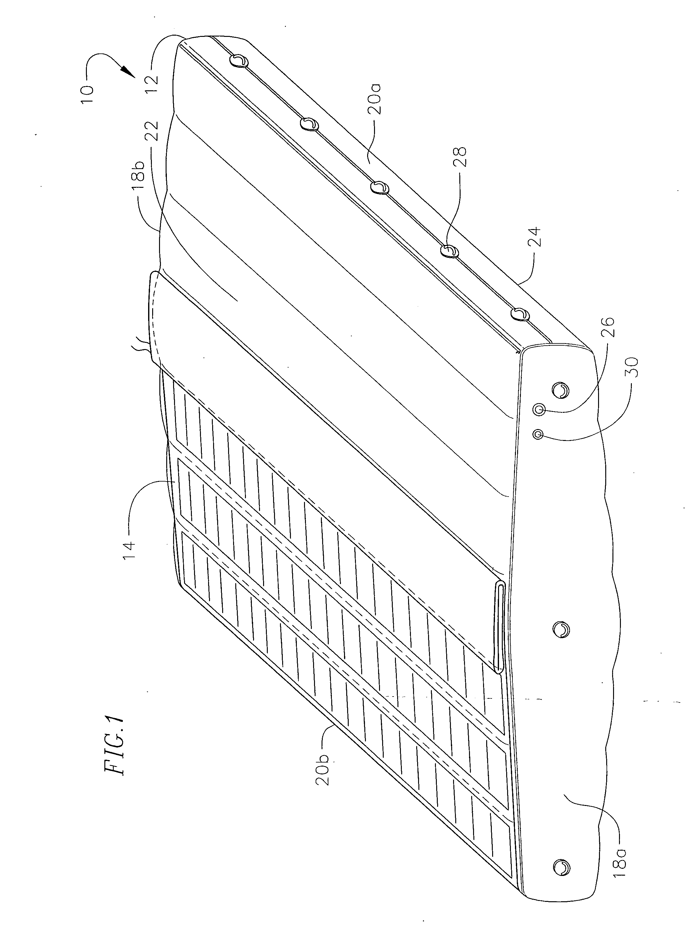
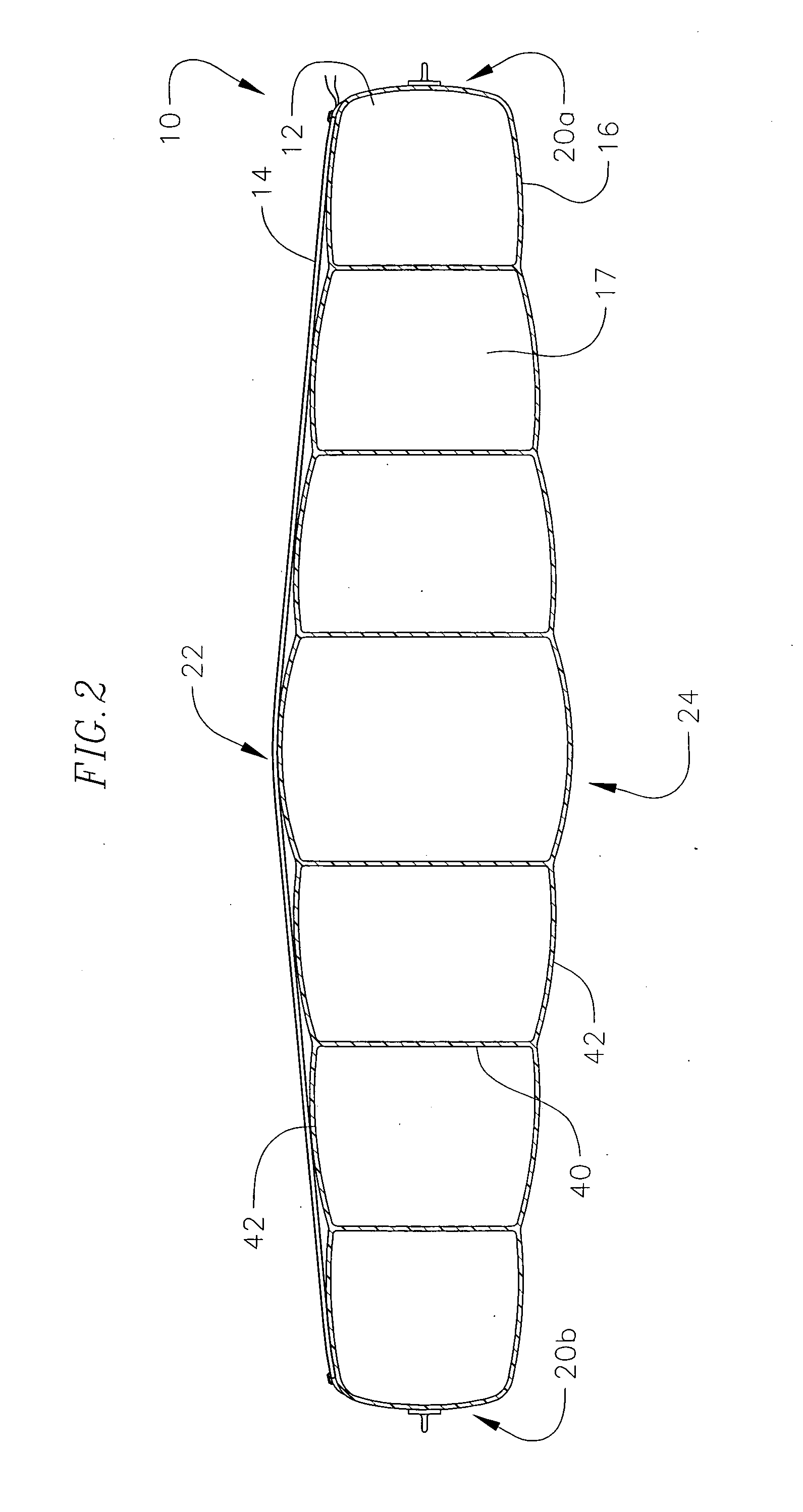
[0029] The present invention is directed to a photovoltaic floatation device, which comprises at least one floatation element, capable of floating on water, and at least one photovoltaic module attached thereto. Having generally described some of the features of the present invention, in the following description, reference is made to the accompanying drawings, which form a part hereof and that show by way of illustration specific embodiments in which the invention may be practiced. It is to be understood that other embodiments may be utilized as structural changes may be made without departing from the scope of the present invention.

[0030] Referring to FIG. 1, one embodiment of the present invention provides a photovoltaic floatation device 10, which comprises a single floatation element 12 with a photovoltaic (PV) laminate panel 14 attached thereon. The floatation element 12 is inflatable and can be comprised for example of material such as PVC, TPO or Hypalon. However one skille...


PUM


Abstract

A device and system for generating electricity with a photovoltaic floatation device is provided. The device comprises one or more photovoltaic cells, which are attached to a panel that is removably attached to a floatation element. The device allows users to utilize the surface areas of water for placement of photovoltaic cells. Multiple devices can be mechanically connected to allow for the formation of one or more photovoltaic floatation device grids. The system comprises one or more photovoltaic floatation devices that are anchored to a particular area in a body of water and are electrically connected to one or more inverters.

Description

CROSS-REFERENCE TO RELATED APPLICATION(S) [0001] This Application claims the benefit of U.S. Provisional Application Ser. No. 60 / 740,559 filed on Nov. 28, 2005, which is incorporated herein by reference.FIELD OF THE INVENTION [0002] The present invention relates to a floatation device with a photovoltaic panel having photovoltaic modules. The device is able to float on water and generate electricity. DESCRIPTION OF RELATED ART [0003] Solar energy has received increasing attention as an alternative renewable, non-polluting energy source to produce electricity as a substitute to other non-renewable energy resources, such as coal or oil that also generate pollution. Given the increase in the price of non-renewable resources such as oil, it has become even more advantageous for companies and individuals to look to solar energy as a cost saving alternative. However, one drawback of solar energy is that the photovoltaic cells used to generate the electricity require a large amount of spac...

Claims


Application Information

Patent Timeline
Patent Type & Authority Applications(United States)
IPC IPC(8): B63B35/00H01L31/042
CPCB63B35/44B63B2035/4453B63B2209/18Y02E10/50H01L31/042H01L31/048F24J2/5267F24S20/70
Inventor KHOURI, BRUCE M.TABOR, KEVIN D.JURISCH, RANDALL E.DAVIDSON, JOELCASTRO, ROKE A.
Owner SOLAR INTEGRATED TECH
Learn More