Graphics-rendering apparatus

Inactive Publication Date: 2007-10-11
KK TOSHIBA
View PDF16 Cites 40 Cited by
  • Summary
  • Abstract
  • Description
  • Claims
  • Application Information

AI Technical Summary

Benefits of technology

[0013] One of objects of the present invention is to provide a graphics-rendering apparatus and a graphics-rendering m

Problems solved by technology

This method is simple and hence is characterized by very stable operation, but has a drawback of a necessity for making a determination of rendering for each point, thereby entailing very high processing cost.
Thus, in relation to determination of a drawing, the method (2) entails high processing cost, as does the method (1).
However, cost of rendering operation is curtailed, and hence the method (2) is expected to become faster than the method (1).
However, triangulation requires complicated processing, and hence stability of complicated processing may pose a problem.
When a polygon desired to be drawn has a very complicated shape, there also arises a problem of triangulation processing involving a very large cost.
Since the method is based on the premise that a group of triangles are rendered by use of a graphics LSI or the like, the LSI cannot be used

Method used


Image

  • Graphics-rendering apparatus
  • Graphics-rendering apparatus
  • Graphics-rendering apparatus

Examples


first embodiment

[0058] A first embodiment of the present invention will now be described.

[0059] The first embodiment shows an example graphics-rendering apparatus which takes, as an input, a vector data group showing the outline of a polygon; and which selects high-speed polygon rendering operation according to the status of resources in the apparatus achieved during rendering operation to thus perform rendering operation.

Overall Configuration

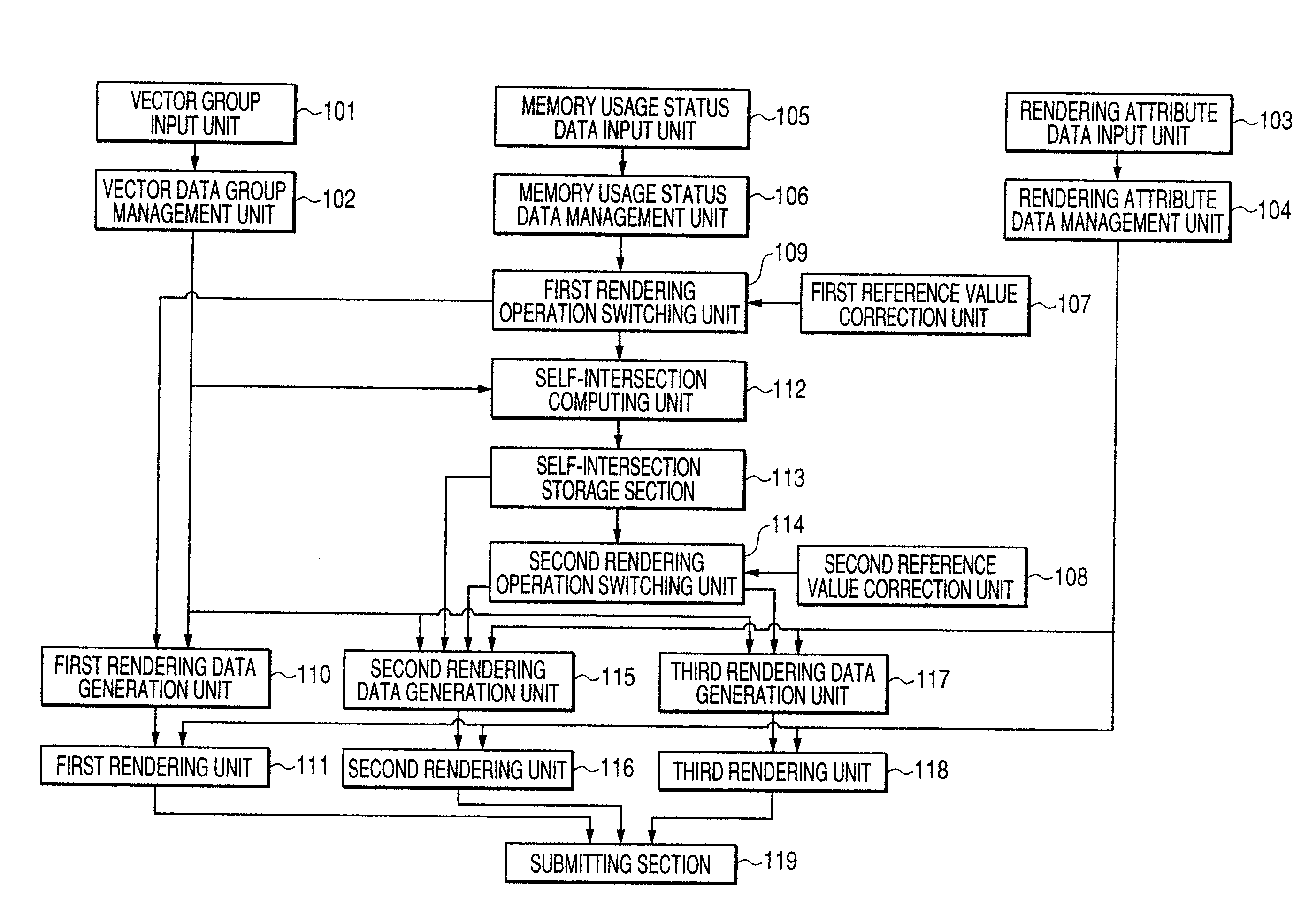
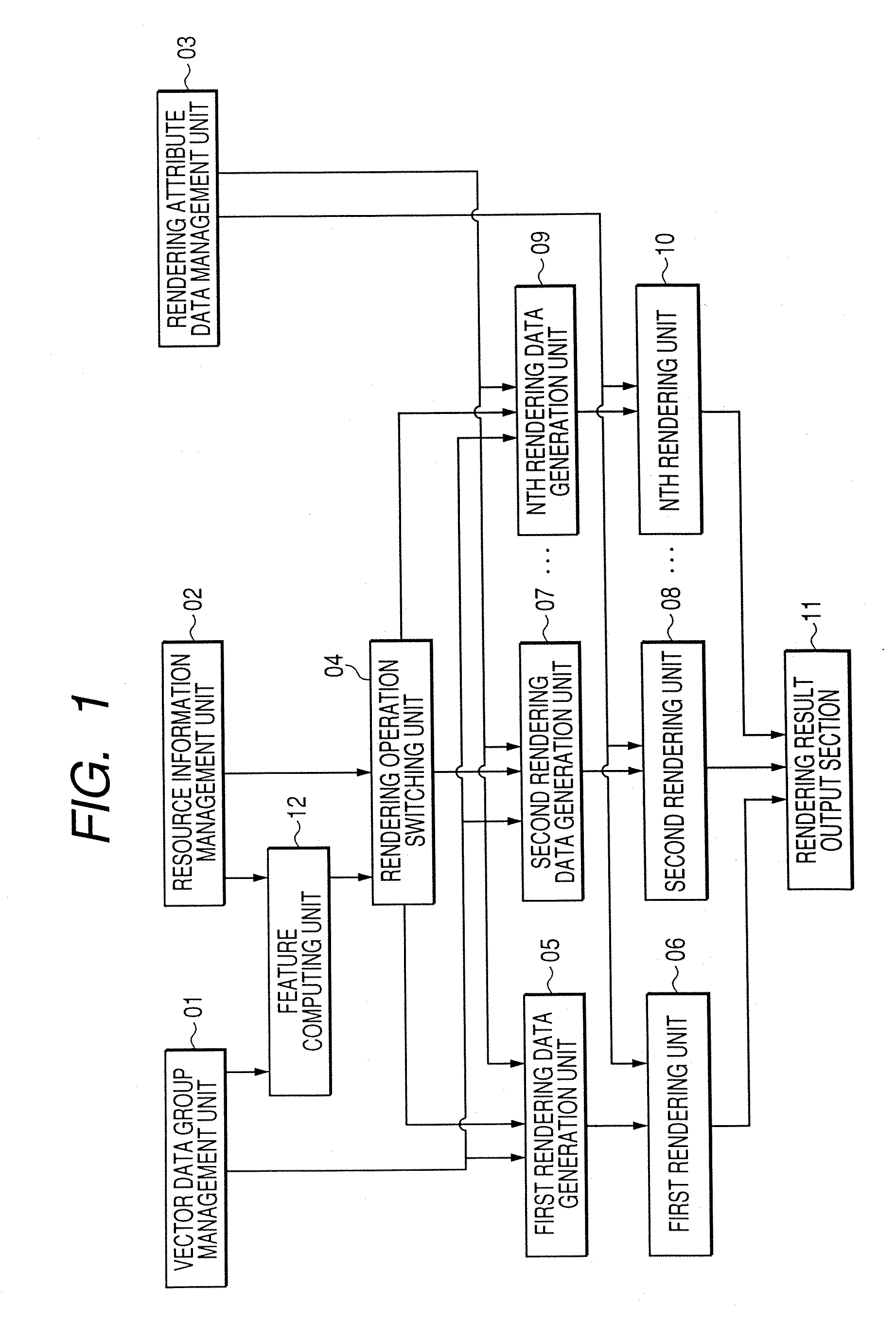
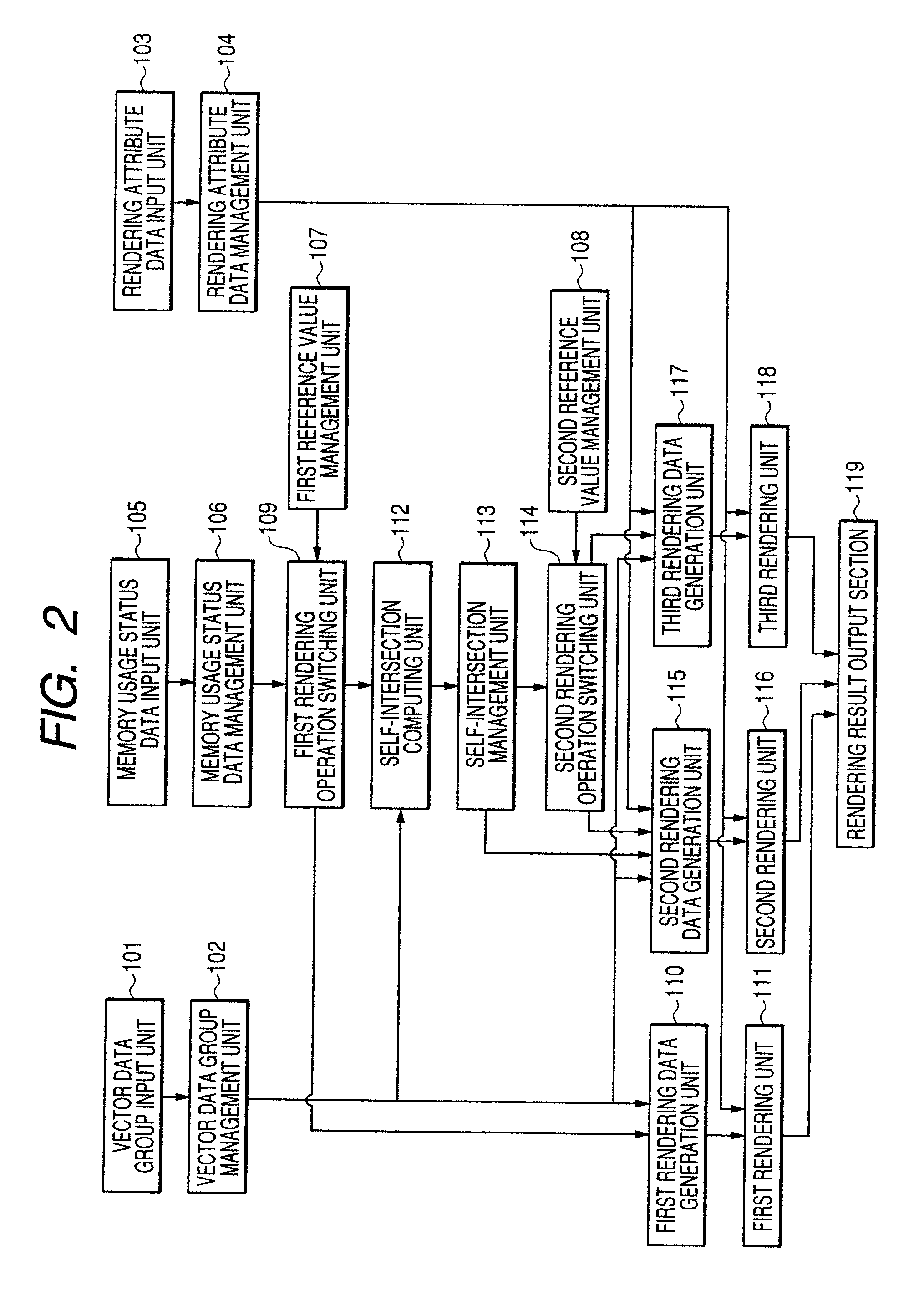
[0060]FIG. 2 is a block diagram of a graphics-rendering apparatus according to the first embodiment.

[0061] The graphics-rendering apparatus of the first embodiment includes: a vector data group input unit 101 for inputting a vector data group representing the outline of a polygon; a vector data group management unit 102 for managing a vector data group which represents the outline of the polygon and has been input through the vector data group input unit 101; a rendering attribute data input unit 103 for inputting rendering attribute data representing att...

second embodiment

[0170] The second embodiment shows an example graphics-rendering apparatus which takes, as inputs, vector data pertaining to a sweep line and vector data pertaining to a shape swept along a sweep line and which selects high-speed rendering of a graphic object to be swept against the backdrop of the apparatus during rendering operation, thereby performing rendering operation.

[0171]FIG. 14 shows a graphics-rendering apparatus according to the second embodiment of the present invention. The graphics-rendering apparatus of the second embodiment includes: a sweep line data input unit 1101 for inputting a vector data group showing a sweep line; a sweep line data management unit 1102 for storing the sweep line data input through the sweep line data input unit 1101; a sweep shape data input unit 1103 for inputting a vector data group showing a shape to be swept; a sweep shape data management unit 1104 for managing the sweep shape data input through the sweep shape data input unit 1103; a r...


PUM


Abstract

Graphics-rendering operation is performed by a procedure including: inputting a vector data group representing the shape of a graphic object to a vector data group management unit; inputting, to a rendering attribute data management unit, rendering attribute data representing information pertains to internal attributes of the graphic object; inputting resource information indicating a usage status into a resource information management unit; reading the managed vector data group from the vector data group management unit; computing a feature indicating the geometrical feature of the input graphic object by means of the feature computing unit; reading the computed graphic feature level and the resource information managed by the resource information management unit; effecting switching to generation of optimum rendering data; reading the vector data group managed by the vector data group management unit and the rendering attribute data managed by the rendering attribute data management unit; generating rendering data; reading the generated rendering data and the rendering attribute data managed by the rendering attribute data management unit; and performing rendering operation.

Description

RELATED APPLICATION [0001] The present disclosure relates to the subject matter contained in Japanese Patent Application No. 2006-088705 filed on Mar. 28, 2006, which is incorporated herein by reference in its entirety. FIELD [0002] The present invention relates to graphics-rendering processing performed in electronic devices, such as a computer, a digital AV device, and a communications device. BACKGROUND [0003] Various methods for rendering an arbitrary polygon have been developed. The methods include (1) a point-based method, (2) a raster-line-based method, (3) a triangle-based method, and (4) a stencil-buffer-based method. [0004] The method (1) is a method for determining rendering with regard to respective points (pixels) included in a rendering area and performing rendering operation on a per-point (pixel) basis. In order to speed up rendering operation, various contrivances, such as deletion of useless rendering areas or simplifying a determination of a drawing at each of the...

Claims


Application Information

Patent Timeline
IPC IPC(8): G06T11/20G06T11/40
CPCG06T11/00G06T11/203G06T11/206G06T11/40G09G5/20G06T1/00G06T11/20G06T1/20
Inventor HIGUCHI, YASUKAZUMIHARA, ISAO
Owner KK TOSHIBA
Why Eureka
Try Eureka