Power supply particularly for a meter-bus

a power supply and meter bus technology, applied in emergency protective circuit arrangements, emergency protective arrangements for limiting excess voltage/current, instruments, etc., to achieve the effect of stabilizing the off state and preventing jitter

Active Publication Date: 2007-10-11
NETWORKED ENERGY SERVICES CORP
View PDF4 Cites 10 Cited by
  • Summary
  • Abstract
  • Description
  • Claims
  • Application Information

AI Technical Summary

Benefits of technology

[0004] A fault tolerant power supply is described. A sensing circuit senses the output current. A switching circuit, coupled to the sensing circuit, has an off state during which the flow of output current is interrupted. A feedback path in the switching circuit reinforces the off state once a pred...

Problems solved by technology

The implementation of physical layer presents several challenges e...

Method used


Image

  • Power supply particularly for a meter-bus
  • Power supply particularly for a meter-bus
  • Power supply particularly for a meter-bus

Examples


Embodiment Construction

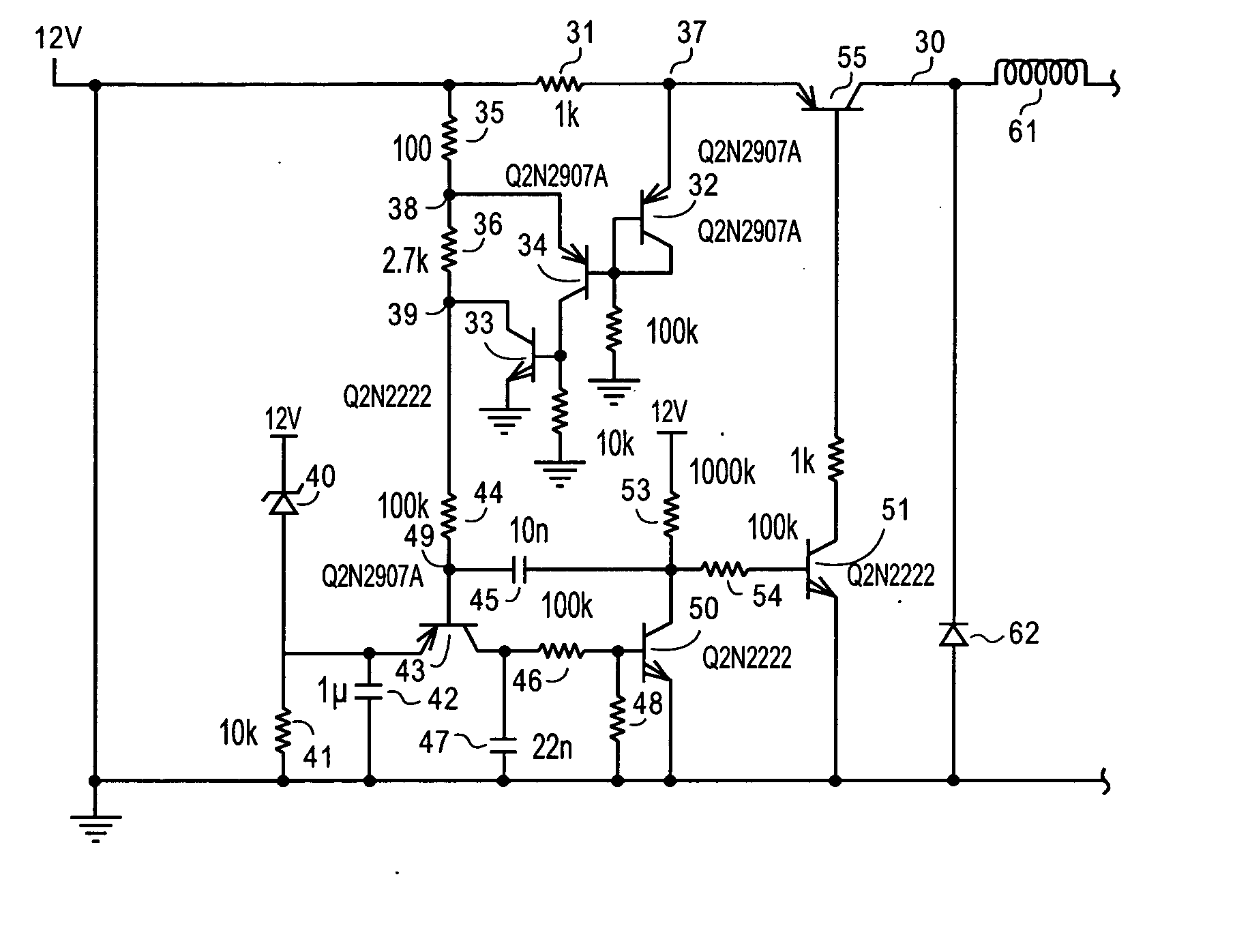
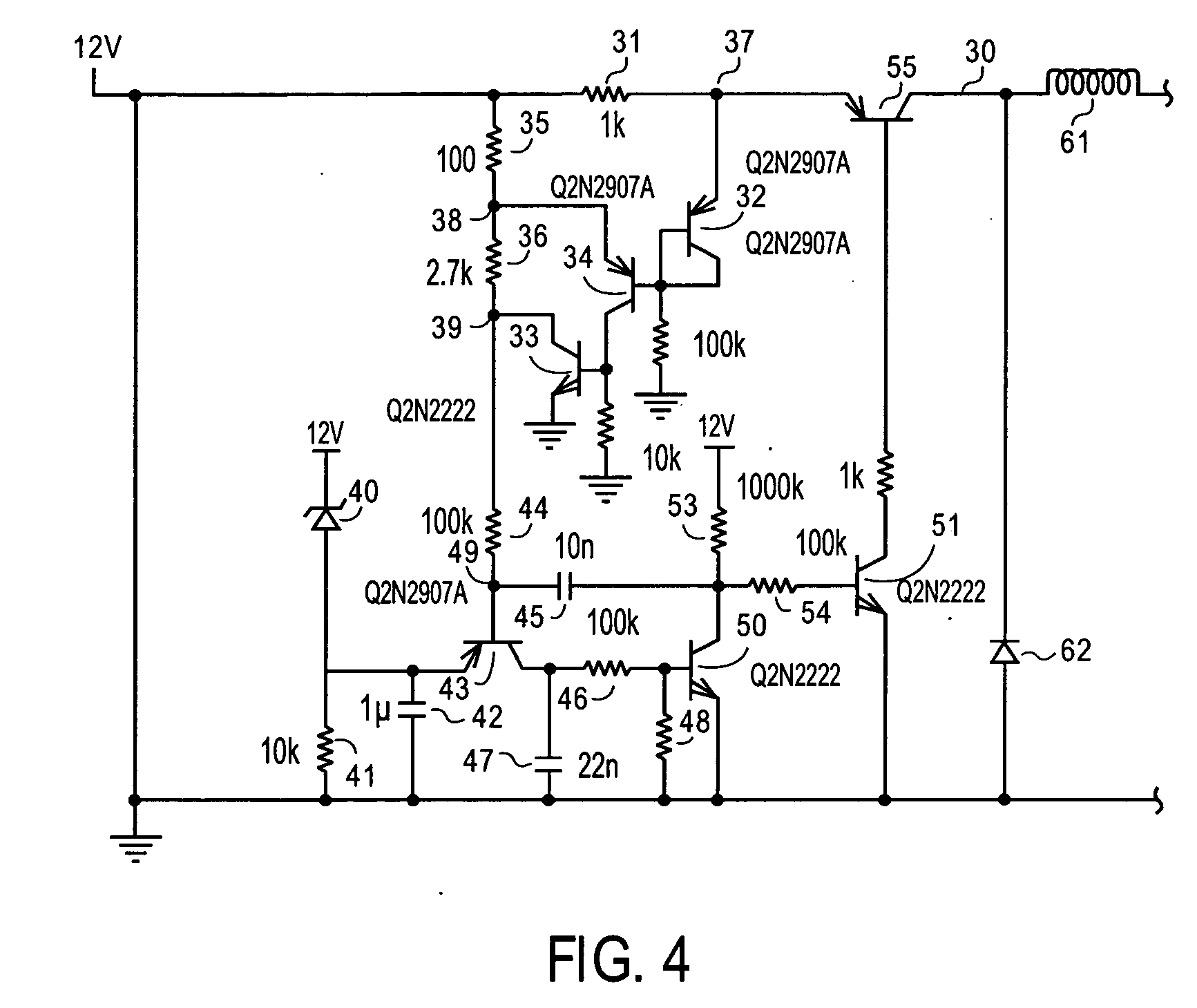
[0009] A fault tolerant power supply particularly suited for M-BUS is described. In the following description, numerous specific details are set forth, for instance, in the schematic of FIG. 4, a specific configuration with specific values for resistors and capacitors as well as specific transistors is set forth. It will be appreciated that these details are used to provide a thorough understanding of the present invention, and other circuit configuration and values may be used within the scope of the present invention.

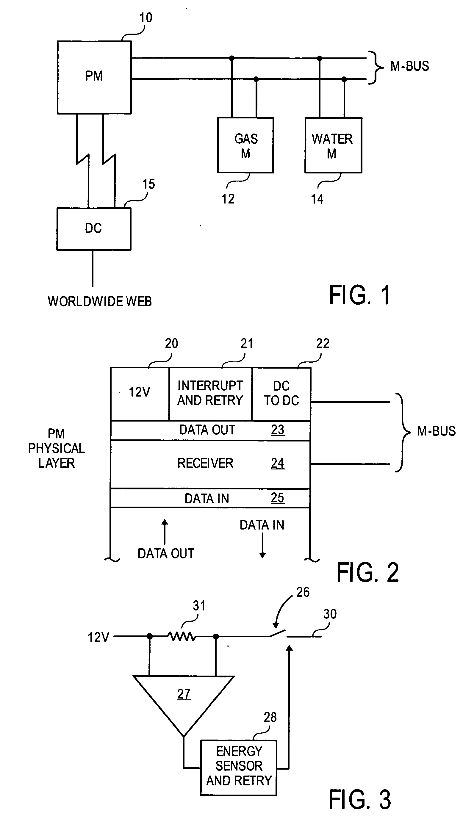
[0010]FIG. 1 illustrates a typical arrangement in which the M-BUS is used. A power meter 10, which is a master under the M-BUS standard, communicates with several slaves such as a gas meter 12 and a water meter 14. As mentioned earlier, sensors, actuators, and other devices may be coupled to the M-BUS. The power meter 10, for instance, may poll the gas and water meters to obtain readings over the M-BUS. Several power meters 10 may be coupled to a data concentrator 15...


PUM


Abstract

A power supply providing current interruption based on the energy from the supply over a sliding window of time is disclosed. The output current from the supply is periodically reestablished.

Description

FIELD OF THE INVENTION [0001] The invention relates to the field of power supplies, particularly fault tolerant power supplies. PRIOR ART AND RELATED ART [0002] A standardized serial bus system for the remote reading of meters and various sensors, has been adopted in Europe. The so-called meter-bus or M-BUS permits, for instance, a power meter to act as a master / gateway for other household meters such as gas and water meters. The M-BUS interconnects the master (e.g. power meter) with the slaves (e.g. gas and water meters). Other sensors such as temperature sensors and actuators to, for example, shed electrical loads, may also be coupled to the M-BUS. The physical and link layer of the M-BUS is set forth in EN 13757-2 and the application layer in EN13757-3. [0003] The implementation of physical layer presents several challenges especially in the design of a fault tolerant power supply and a receiver. These are discussed in connection with FIGS. 1 and 2. SUMMARY OF THE INVENTION [0004...

Claims


Application Information

Patent Timeline
IPC IPC(8): H02H7/00
CPCG01R22/063G01R21/133
Inventor VANRUYMBEKE, GILLESROBINSON, ANDREW
Owner NETWORKED ENERGY SERVICES CORP
Why Eureka
Try Eureka