Ct scanner with automatic determination of volume of interest

a ct scanner and volume technology, applied in tomography, instruments, applications, etc., can solve the problems of time-consuming and labor-intensive selection of volume of interest, and achieve the effect of reducing the exposure of patients to x-rays

Inactive Publication Date: 2007-10-11
XORAN TECH
View PDF46 Cites 26 Cited by
  • Summary
  • Abstract
  • Description
  • Claims
  • Application Information

AI Technical Summary

Benefits of technology

[0008] When operating in an automatic mode, the CT scanner then compares the initial images to a previous CT image (either a pre-operative CT scan, a previously-updated CT scan or generic data). Based upon the comparison, the CT scanner determines where changes to the anatomy have occurred (e.g., because of the surgery so far). The volume where changes have occurred, plus some defined margin, becomes the volume of interest. The CT scanner then collimates an x-ray source to perform an intra-operative updated CT scan of only the volume of interest. The CT scanner updates the previous CT scan(s) with the new images of the volume of interest from the intra-operative updated CT scan to create a fully updated CT image, reducing x-ray exposure of the patient.
[0010] Preferably, the CT scanner provides a user interface that offers the surgeon the option of performing either the fully automatic volume of interest determination update scan or a surgeon-selected volume of interest determination update scan with automatic registration of the volume of change by the CT scanner.

Problems solved by technology

In matters like intracranial surgery, the tolerance for variations is low, thus even small changes between the image and actual subject may cause problems and make the surgery less effective.
However, selecting the volume of interest can be time-consuming if the surgeon is required to find the volume of interest on the pre-operative CT scan.

Method used


Image

  • Ct scanner with automatic determination of volume of interest
  • Ct scanner with automatic determination of volume of interest
  • Ct scanner with automatic determination of volume of interest

Examples


Embodiment Construction

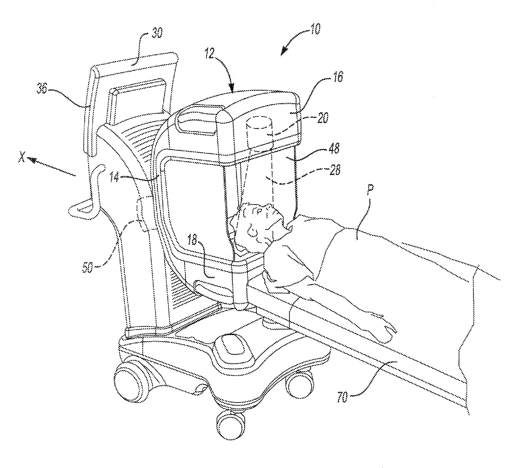
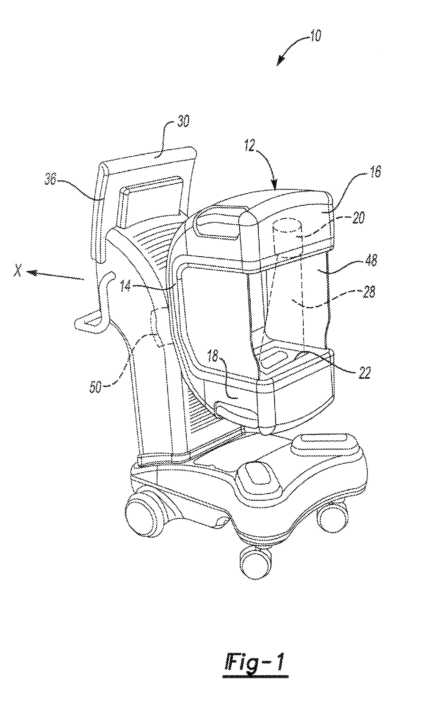
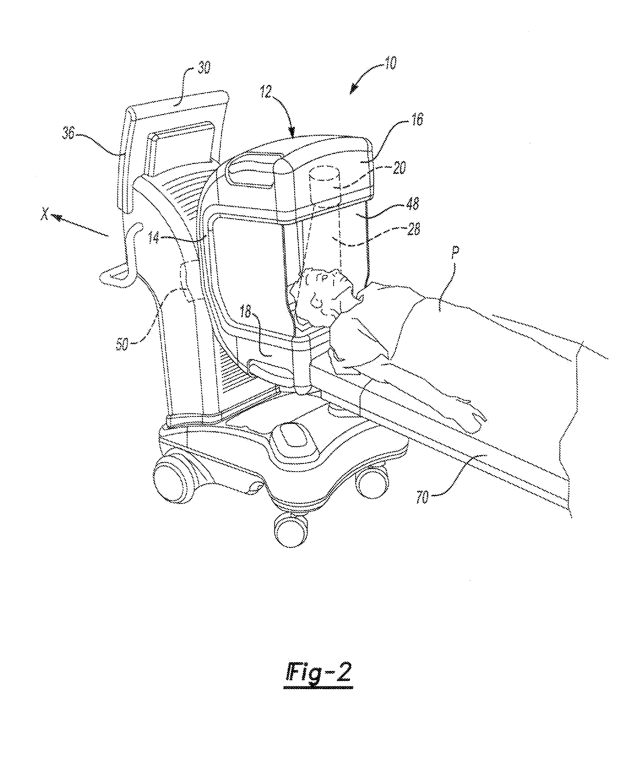
[0019]FIG. 1 illustrates an intra-operative CT scanner 10 of a surgical imaging system of the present invention including a gantry 12 that supports and houses components of the CT scanner 10. Suitable CT scanners 10 are known. In one example, the gantry 12 includes a cross-bar section 14, and a first arm 16 and a second arm 18 each extend substantially perpendicularly from opposing ends of the cross-bar section 14 to form the c-shaped gantry 12. The first arm 16 houses an x-ray source20 that generate x-rays 28. In one example, the x-ray source 20 is a cone-beam x-ray source. The second arm 18 houses a complementary flat-panel detector 22 spaced apart from the x-ray source 20. The x-rays 28 are directed toward the detector 22 which includes a converter (not shown) that converts the x-rays 28 from the x-ray source 20 to visible light and an array of photodetectors behind the converter to create an image. As the gantry 12 rotates about the patient P, the detector 22 takes a plurality o...


PUM

PropertyMeasurementUnit
CTaaaaaaaaaa
volumeaaaaaaaaaa
field of viewaaaaaaaaaa

Abstract

A CT scanner automatically determines a volume of change based upon anatomical changes in a patient. During surgery, the CT scanner takes a sufficient number of two-dimensional initial images using a full field of view. The CT scanner compares the initial images to pre-operative data. Based upon the comparison, the CT scanner automatically determines the volume of change plus some margin to define a volume of interest. The CT scanner then collimates an x-ray source to perform an intra-operative updated CT scan of the volume of interest. The CT scanner updates the pre-operative data with the data from the intra-operative updated CT scan of the volume of interest to form a fully updated three-dimensional CT image. The initial images and the pre-operative data can be taken at a lower resolution than the intra-operative updated CT scan of the volume of interest to reduce the x-ray exposure of the patient.

Description

REFERENCE TO RELATED APPLICATIONS [0001] This application claims priority to U.S. Provisional Application Nos. 60 / 786,638 filed Mar. 28, 2006 and 60 / 851,196 filed Oct. 12, 2006.BACKGROUND OF THE INVENTION [0002] The present invention relates generally to a surgical imaging system including a CT scanner that automatically determines a volume of interest of a patient. [0003] It is sometimes desirable to be able to take a CT scan of a patient during surgery. For example, a surgeon may want to check the progress of the surgery (e.g., to determine whether a problem has been completely corrected or whether a tumor has been completely removed, etc). [0004] For image-guided surgery, it is sometimes desirable to periodically update a pre-operative CT scan of the patient. The relevant volume of the patient may have shifted between the time the pre-operative image was taken and the time of surgery. This is especially true once surgery has begun. For example, in cranial surgery, a shape of an i...

Claims


Application Information

Patent Timeline
Patent Type & Authority Applications(United States)
IPC IPC(8): H05G1/60A61B6/00G01N23/00G21K1/12
CPCA61B6/032A61B6/12A61B6/4405A61B6/4441G01N2223/612A61B6/488A61B6/5235G01N23/046G01N2223/419A61B6/469
Inventor SUKOVIC, PREDRAGSTAYMAN, JOSEPH WEBSTERSARMENT, DAVID PHILLIPECLINTHORNE, NEAL
Owner XORAN TECH
Why Eureka
Try Eureka