

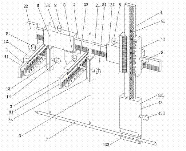
Three-dimensional coordinate-positioning drilling guiding system
A technology of three-dimensional coordinates and guidance system, applied in bone drill guidance, medical science, surgery, etc., can solve the problems of high price, long learning curve, complex structure of surgical navigation system, etc., achieve accurate drilling and avoid X-ray exposure , reduce the effect of X-ray exposure
- Summary
- Abstract
- Description
- Claims
- Application Information
AI Technical Summary
Problems solved by technology
Method used
Image

Examples
Embodiment 1
[0035] Embodiment 1: femoral neck fracture, reference Figure 4 .
[0036] After the fracture is reduced, the body surface locator is fixed on the ilium, the grid plate is placed in front of the hip joint, adjusted to make it horizontal, and perpendicular to the grid plate to take pictures or perspective.
[0037] According to the image, draw the position of the first guide pin, set A as the center point of the femoral head image, D as the target point, point C (reference point) where the guide pin intersects with the centerline of the long axis of the femur, and AB as A The vertical line from the point to CD, insert the thin needle vertically from the body surface projection point of point A, measure the distance from point A to the body surface projection point as h, and set the radius of the femoral head as r, then point D on the x1 axis vernier caliper The coordinate is AB, and the coordinate on the y-axis vernier caliper is r+h+positioning pin length L.
[0038] Insert ...
Embodiment 2
[0040] Example 2: positioning of femoral intramedullary nail insertion point, refer to Figure 5 .
[0041] Fix the body surface locator in front of the proximal femur, adjust the grid plate horizontally, and take pictures or see through the grid plate vertically.
[0042] like Figure 5 , as the centerline of the long axis of the femur, select two points AB, and insert the positioning needle vertically from the body surface projection points of the two points AB to the femoral surface, the coordinate of the center point of the cross-section of point A on the x1-axis vernier caliper is 0, and on the y-axis The coordinates on the vernier caliper are the lateral radius of the femur at point A plus the length L of the positioning pin, and the coordinates of the center point of the section at point B are determined similarly. Fix the positioning pins respectively, adjust and fix the vernier according to the coordinates, flex and adduct the hip joint, and drill the guide pins fro...
Embodiment 3
[0043] Embodiment 3: supracondylar fracture of humerus, reference Figure 6 .
[0044] After reduction, the body surface locator is fixed behind the elbow joint at the lower end of the humerus, and radiographs or perspectives are taken.
[0045] Select the target point at the proximal end of the fracture, as shown in point A in the figure. Let the thickness at point A be h (which can be measured on the lateral view). 1 / 3h plus positioning pin length and 2 / 3h plus positioning pin length. Insert the positioning needle vertically from the body surface projection point of point A, and drill the Kirschner wire from the lateral condyle and medial condyle respectively according to the coordinate adjustment.
PUM
 Abstract
Description
Claims
Application Information