
Technique for securing a suture

a technology for sutures and securing screws, which is applied in the field of medical procedures, can solve the problems of reducing the strength of the suture, complicated overall design, and complicated manufacturing process of glue used in the manufacturing process, and achieves the effect of increasing the tension of the suture and increasing the holding power

Inactive Publication Date: 2007-10-11
ST JUDE MEDICAL COORDINATION CENT
View PDF16 Cites 401 Cited by
  • Summary
  • Abstract
  • Description
  • Claims
  • Application Information

AI Technical Summary

Benefits of technology

[0007] The present invention provides a technique to connect the ends (or other portions) of a suture used in sealing an incision in a blood vessel. In the present invention, portions of the suture are joined together (for example, to form a loop) by embedding one portion of the suture within another portion of the suture

Problems solved by technology

For example, the use of glue in the manufacturing process complicates manufacturing because the glue has to be applied properly, has to be immobilized while drying, etc.
Knot(s) reduce the strength of a suture, and make the overall design more complicated because care must be taken to make sure that the knot(s) pass through various components (e.g., components of an introducer device used to guide and push the sealing and / or locking members in place during a sealing procedure).

Method used


Image

  • Technique for securing a suture
  • Technique for securing a suture
  • Technique for securing a suture

Examples


Embodiment Construction

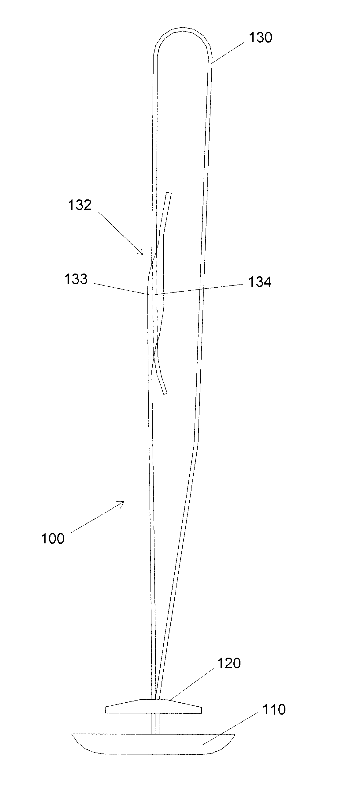
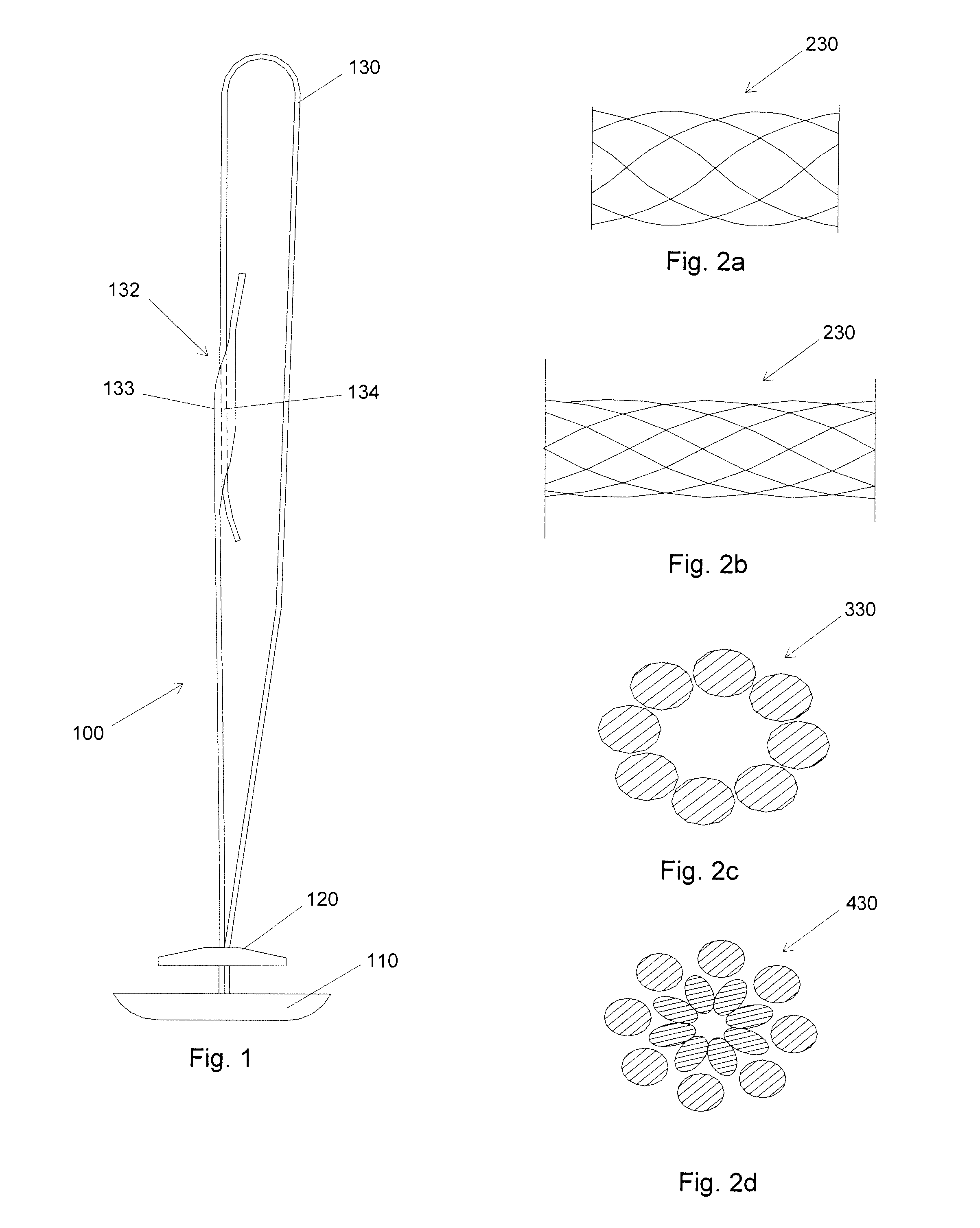
[0017]FIG. 1 illustrates a first preferred embodiment 100. As shown in FIG. 1, first preferred embodiment 100 includes an inner seal 110, an outer locking element 120, and a suture 130. The suture 130 has a portion 132 wherein a first portion 134 of the suture is embedded in a second portion 133 of the suture, as shown in FIG. 1. In this manner, as tension in the suture increases, the portions 133 and 134 are held together due to portion 133 contracting (in cross section) and exerting friction on portion 134.

[0018]FIGS. 2a to 2d illustrate some examples of sutures which may be employed in the present invention. FIG. 2a shows a suture 230 in a relaxed state and FIG. 2b shows the same suture 230 in a state of tension. FIG. 2c illustrates a suture 330 having a single layer of filaments and FIG. 2d shows a suture 430 having two layers of filaments. Other suture designs may be used in the invention.

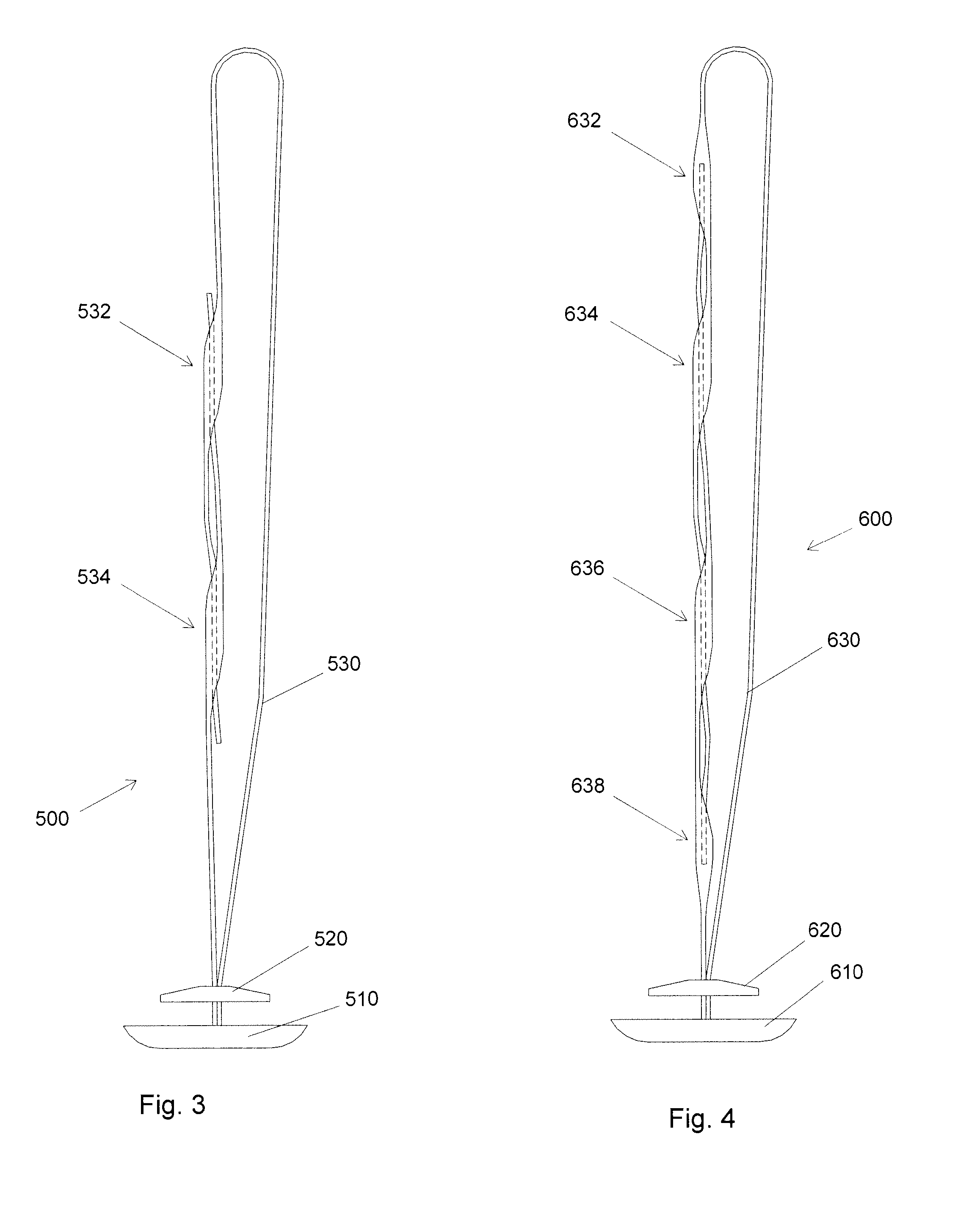
[0019]FIG. 3 illustrates a second embodiment 500. The second embodiment includes an inne...


PUM


Abstract

A device to seal an incision in a blood vessel includes an inner member and an outer member. A suture connects the inner member and the outer member. A first portion of the suture is embedded within a second portion of the suture such that as tension in the suture increases the first and second portions are held together. According to certain embodiments, the second portion is not part of a first suture portion, and both the first and second portions are used to retain the outer member in place. A method of making such a device is also described.

Description

CROSS-REFERENCE TO RELATED PATENT APPLICATIONS [0001] This application is a continuation-in-part of U.S. application Ser. No. 10 / 805,486, filed Mar. 22, 2004, which in turn claims the benefit of U.S. Provisional Application No. 60 / 530,618, filed Dec. 19, 2003. The entire contents of both of these applications are incorporated herein by reference.BACKGROUND OF THE INVENTION [0002] There are several medical procedures which require access to a patient's vascular system. Access to a patient's vascular system can be provided by making an incision (sometimes called a puncture, wound, or hole) in an artery (or other blood vessel) below the skin surface. At the conclusion of the medical procedure, the incision in the artery must be sealed. [0003] One technique for sealing such an incision is to place an inner seal within the artery and an outer locking element outside the artery in such a fashion as to seal the incision. The seal is made of bioabsorbable materials which are absorbed within...

Claims


Application Information

Patent Timeline
IPC IPC(8): A61B17/04
CPCA61B17/0057A61B17/0487A61B2017/06185A61B2017/0454A61B2017/0459A61B2017/00659
Inventor FALLMAN, DAVID
Owner ST JUDE MEDICAL COORDINATION CENT
Features
  • Generate Ideas
  • Intellectual Property
  • Life Sciences
  • Materials
  • Tech Scout
  • Unparalleled Data Quality
  • Higher Quality Content
  • 60% Fewer Hallucinations
Learn More