Vehicle with variable air intake arrangement

Active Publication Date: 2007-10-18
YAMAHA MOTOR CO LTD
View PDF6 Cites 7 Cited by
  • Summary
  • Abstract
  • Description
  • Claims
  • Application Information

AI Technical Summary

Benefits of technology

[0009] With the vehicle as described in the above paragraph, in which a seal member is disposed between the stationary funnel and the movable funnel, air leakage through the gap between the movable funnel and the stationary funnel can be inhibited or eliminated when the movable funnel is in cooperation with the stationary funnel. With such a construction, a desired amount of air can be supplied to the intake port. In addition, the retention mechanism for retaining the seal member with either one of the stationary funnel and the movable funnel is also provided. Thus, the seal member can be prevented from disengaging from the stationary funnel or the movable funnel. With such a construction, it is possible to inhibit or prevent the seal member from falling off from the stationary funnel or the movable funnel and possibly entering the inside of the engine, thereby preventing damage to the engine.
[0022] Yet another aspect of a preferred embodiment involves the vehicle described above, wherein the seal member comprises a seal portion for contact with one of the stationary funnel and the movable funnel in multiple directions. With this construction, air leakage through the gap between the movable funnel and the stationary funnel can be reduced or eliminated when the movable funnel cooperates with the stationary funnel.

Problems solved by technology

Accordingly, it is difficult to supply a desired amount of air to the intake port.

Method used


Image

  • Vehicle with variable air intake arrangement
  • Vehicle with variable air intake arrangement
  • Vehicle with variable air intake arrangement

Examples


first embodiment

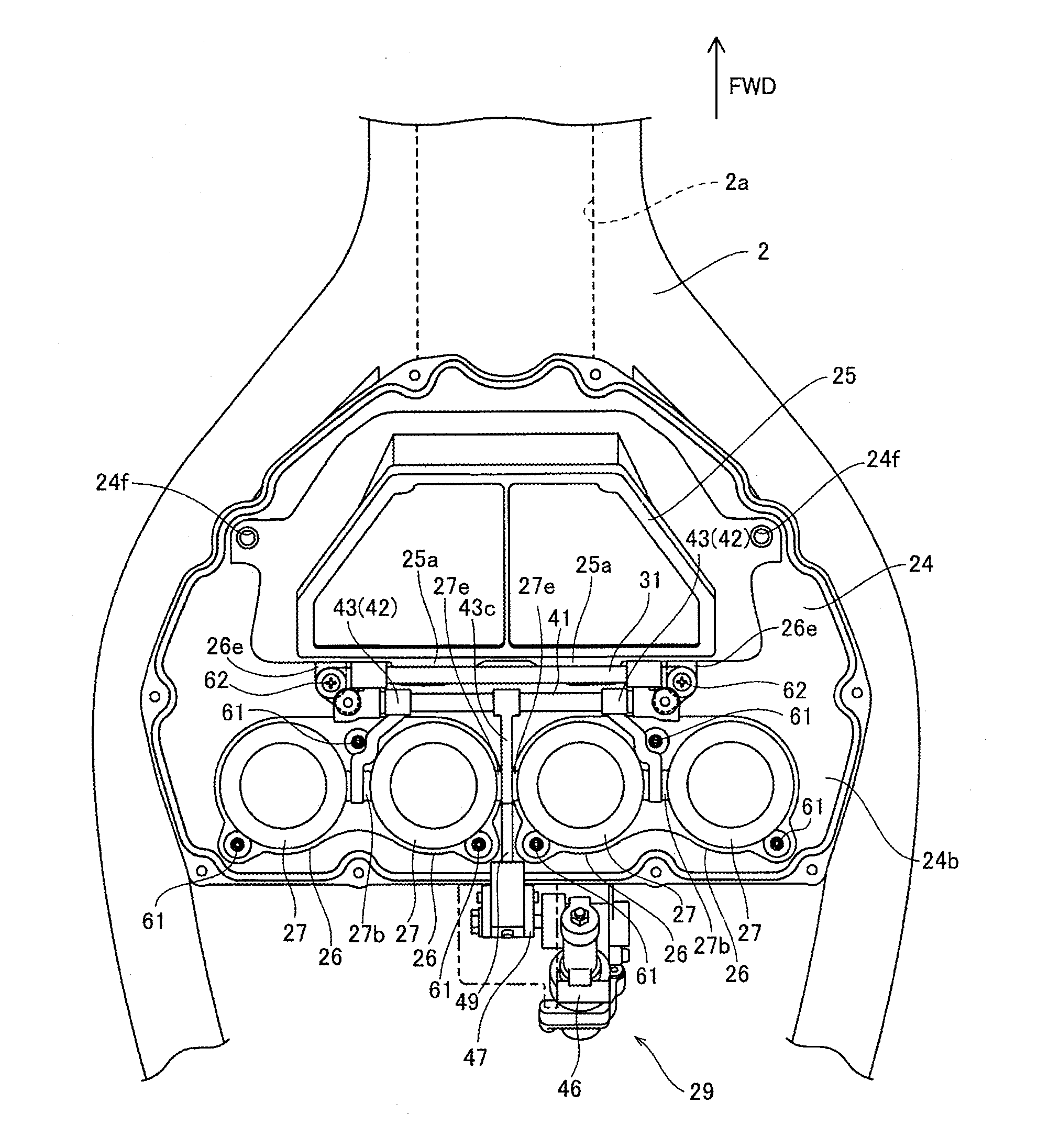
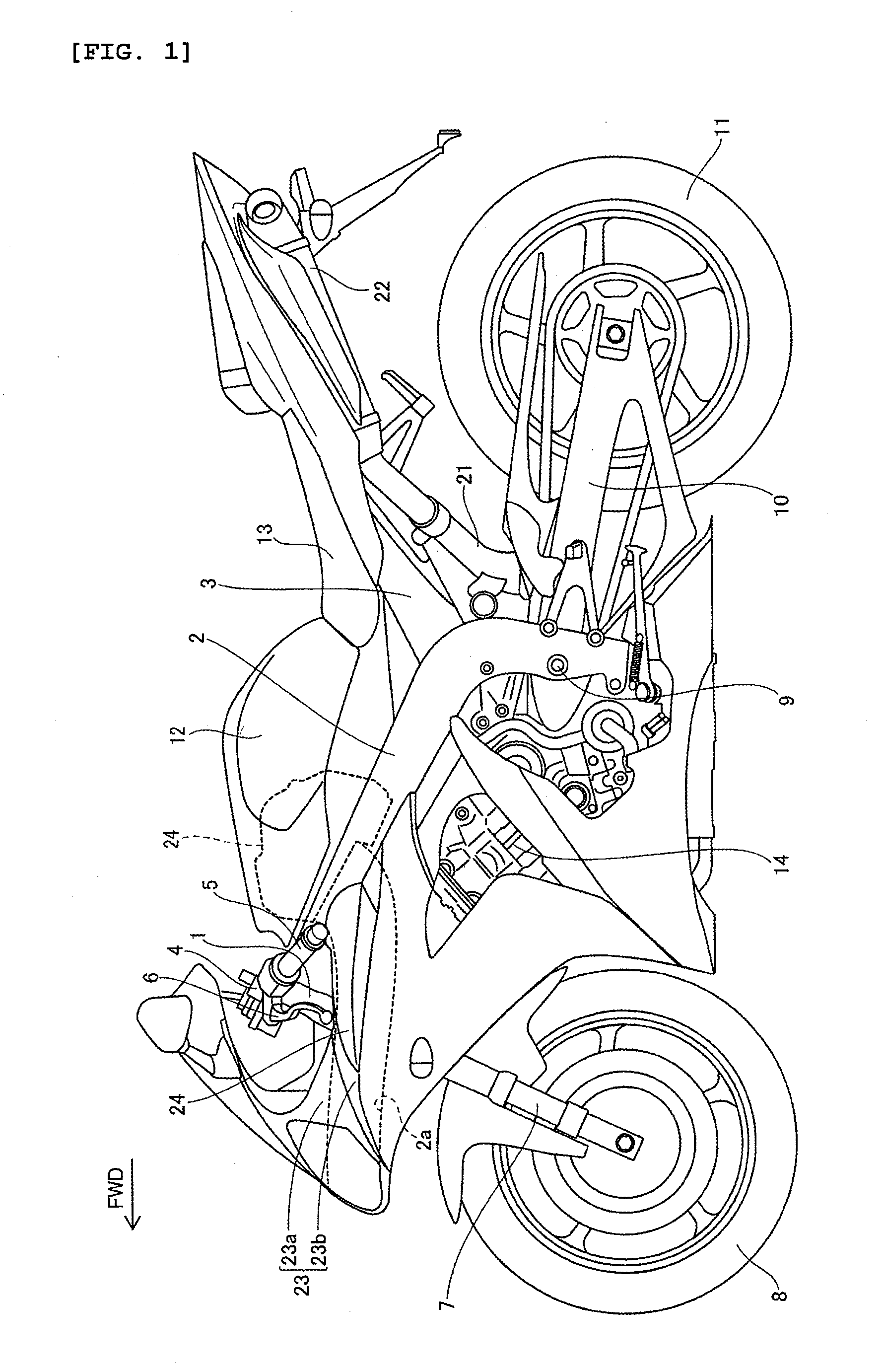
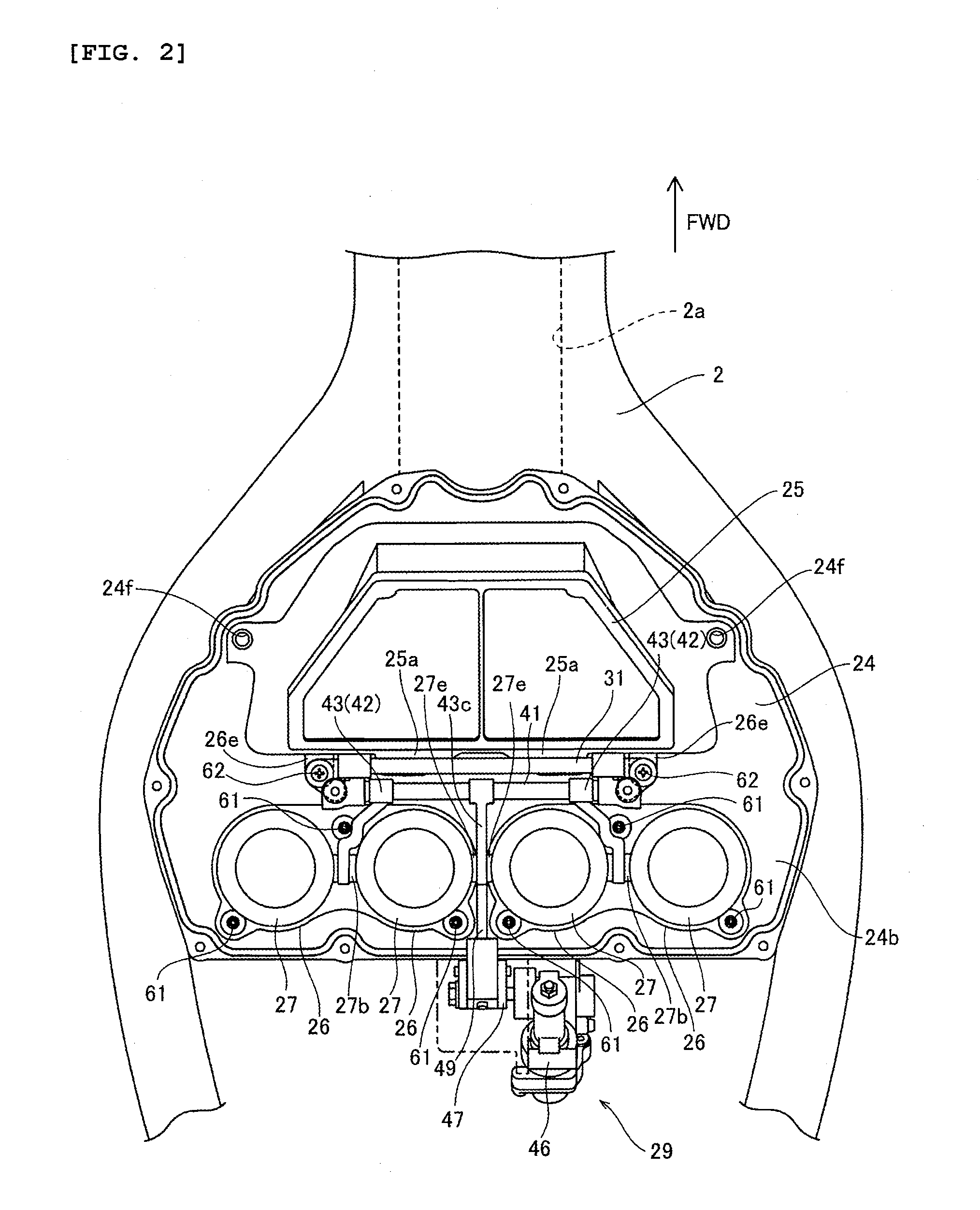
[0053] As shown in FIG. 1, the motorcycle of the first embodiment has a head pipe 1 and a main frame 2 with its front end connected to the head pipe 1. As shown in FIG. 2, the main frame 2 is branched to extend leftward and rightward with respect to the forward direction of the vehicle body (FWD direction indicated by the arrow). The main frame 2 is provided with an air intake passage 2a for introducing air into an air cleaner box 24 described below. As shown in FIG. 1, the main frame 2 is formed to extend rearward and downward. A seat rail 3 extends rearward and upward and is connected to the main frame 2. A steering mechanism 4 is attached to the head pipe 1 for rotational movement. Handlebars 5 are attached to an upper portion of the steering mechanism 4. A clutch lever 6 is attached to the handlebars 5. A front fork 7 is attached to a lower part of the steering mechanism 4. A front wheel 8 is rotatably mounted at the lower end of the front fork 7.

[0054] The front end of a swing ...

second embodiment

[0104] In the second embodiment, as shown in FIG. 23, the seal member 85 is formed with a thick portion, or a first portion 85e with a first axial length and a recessed thin portion, or second portion 85f with a second axial length that is less than the axial length of the first portion 85e. As shown in FIG. 27, a lower part of the support shafts 77b and 77e of the movable funnel 77 is disposed in the recessed part of the second portion 85f. The support shaft 77b is an example of the “shaft part” of the present invention.

[0105] In the second embodiment, as shown in FIGS. 25 and 26, the movable funnel 77 is formed with a recess 77h. As shown in FIG. 26, the seal member 85 is formed with a projection 85g for engagement with the recess 77h. With this construction, the seal member 85 can be more reliably prevented from coming off from the movable funnel 77.

[0106] The structure of the other part of the second embodiment is similar to that of the first embodiment. In the second embodimen...


PUM


Abstract

A vehicle, such as a motorcycle, includes an engine having at least one intake port. An air intake assembly introduces air into the intake port. In one arrangement, the air intake assembly includes a stationary funnel and a movable funnel positioned on the inlet side of the fixed funnel and selectively cooperates with the stationary funnel to deliver air to the intake port of the engine. A seal member creates at least a substantial seal between the fixed funnel and the movable funnel when the funnels are in cooperation with one another. A retention mechanism inhibits the seal member from disengaging with the funnel onto which the seal member is positioned. In one arrangement, the movable funnel is formed with one or more projections and the seal member is formed with one or more recesses that accommodate the projections. The projection may be a flange or a boss, among other possibilities, and the recess is configured to accommodate the specific projection.

Description

RELATED APPLICATIONS [0001] This application is related to, and claims priority from, Japanese Patent Application Nos. 2006-253673, filed Sep. 20, 2006, and 2006-111560, filed Apr. 14, 2006, each entitled “VEHICLE.” The entireties of these applications are hereby incorporated by reference herein and made a part of the present specification. BACKGROUND OF THE INVENTION [0002] 1. Field of the Invention [0003] The present invention relates to a vehicle, and more particularly to a vehicle having a variable length air intake arrangement for introducing air to an intake port of an engine. [0004] 2. Description of the Related Art [0005] Some vehicles incorporate a variable length air intake system. For example, a variable length air intake system shown in Japanese Patent Publication No. 63-182229 includes a stationary intake pipe for introducing air to an intake port of an engine, a movable pipe movably disposed on the air inlet side of the stationary pipe. A rotary arm is positioned on on...

Claims


Application Information

Patent Timeline
IPC IPC(8): F02M35/10
CPCF02M35/10039F02M35/10104F02M35/10216F02M35/10301F02M35/162F02D9/12F02B27/0231F02B27/0294F02M35/02491F02M35/10052F02M35/10065Y02T10/146F02B27/0215Y02T10/12
Inventor SUDOH, TAKEHIKOKOBAYASHI, MAKOTO
Owner YAMAHA MOTOR CO LTD
Why Eureka
Try Eureka