Heat pipe

Inactive Publication Date: 2007-10-18
HON HAI PRECISION IND CO LTD
View PDF12 Cites 18 Cited by
  • Summary
  • Abstract
  • Description
  • Claims
  • Application Information

AI Technical Summary

Benefits of technology

[0008]The present invention relates to a heat pipe. A heat pipe includes a hollow metal casing. The casing has an evaporating section and a condensing section at respective opposite ends thereof, and an adiabatic section located between the evaporating section and the condensing section. A capillary wick is arrang

Problems solved by technology

However, during the phase change of the working media, the resultant vapor and the condensed liquid flows along two opposing directions, which reduces the speed of the condensed liquid in returning back to the evaporating section and therefore limits the maximum heat transfer capacity (Qmax) of

Method used


Image

  • Heat pipe
  • Heat pipe
  • Heat pipe

Examples


Embodiment Construction

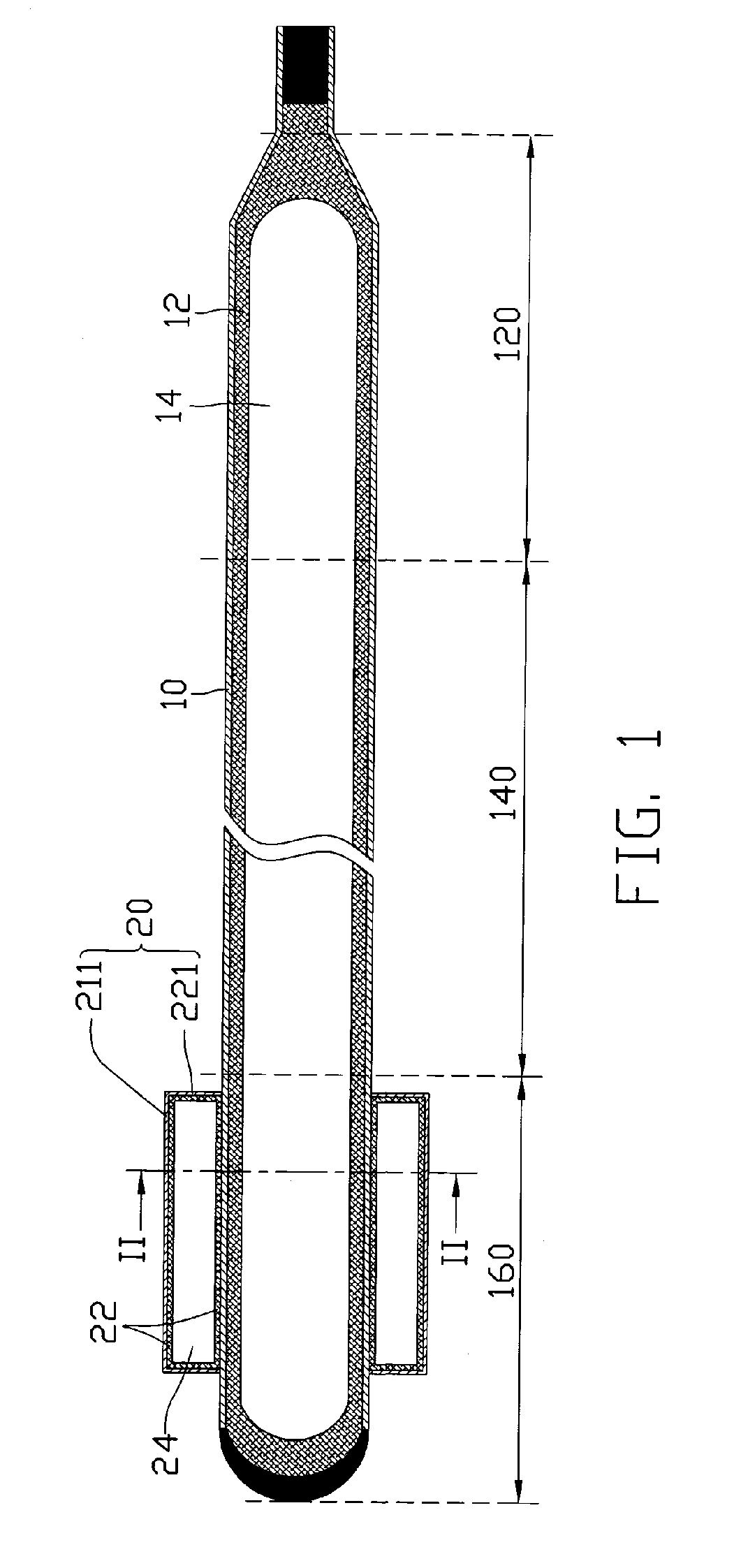
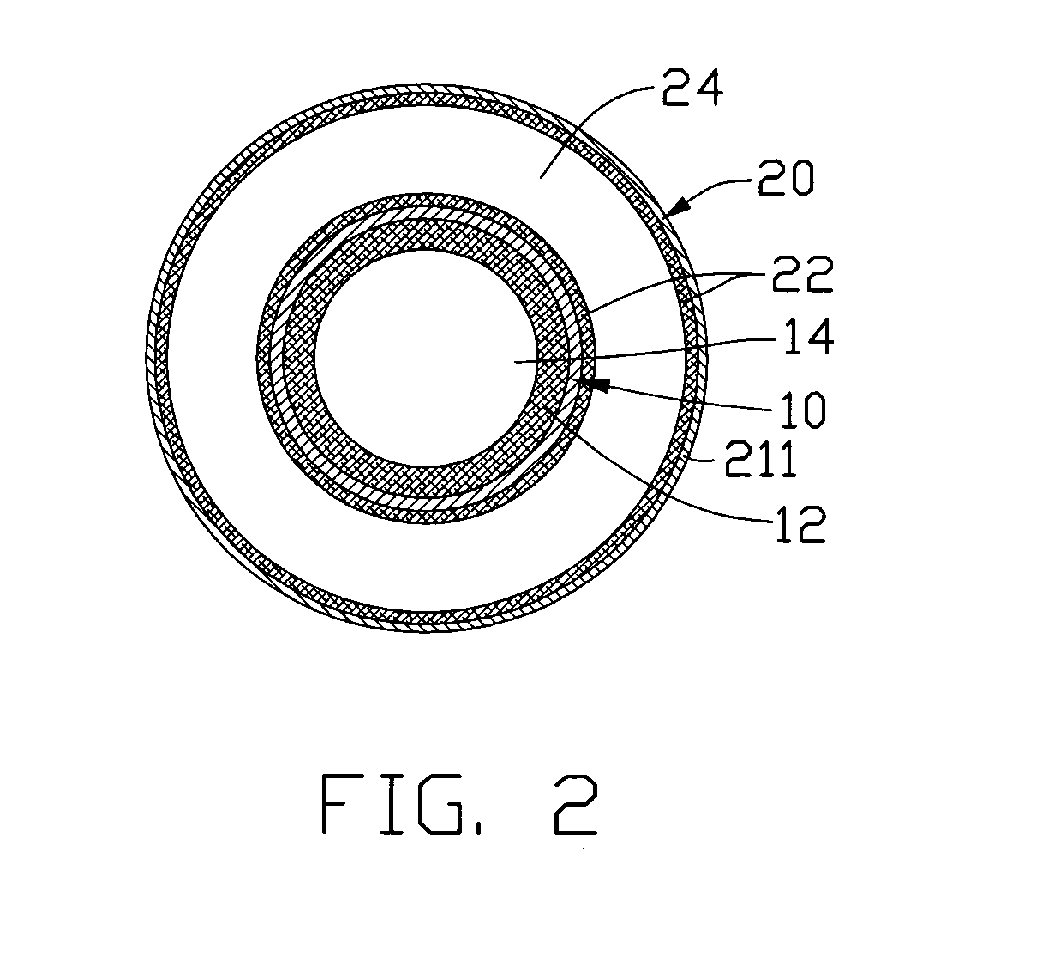
[0018]FIGS. 1 and 2 show a heat pipe in accordance with one embodiment of the present invention. The heat pipe has a cylindrical configuration and includes a metal casing 10 made of highly thermally conductive materials such as copper or copper alloys, a first working fluid (not shown) contained in the casing 10 and a first capillary wick 12 arranged in an inner surface of the casing 10. The casing 10 includes an evaporating section 120 at one end, a condensing section 160 at the other end and an adiabatic section 140 arranged between the evaporating section 120 and the condensing section 160. A sealed heat reservoir 20 is mounted on the condensing section 160. A vapor channel 14 is defined along an axial direction of the heat pipe and is located at a center of the casing 10. The vapor channel 14 is surrounded by an inner surface of the first capillary wick 12 so as to guide vapor to flow therein.

[0019]The heat reservoir 20 has a hollow cylindrical configuration and is made of highl...


PUM


Abstract

A heat pipe includes a hollow metal casing (10). The casing has an evaporating section (120) and a condensing section (160) at opposite ends thereof, and an adiabatic section (140) located between the evaporating section and the condensing section. A capillary wick (12) is arranged at an inner surface of the hollow metal casing. A working fluid is received in the metal casing. A sealed heat reservoir (20) is mounted on the condensing section of the heat pipe to increase heat dissipation area of the heat pipe. The heat reservoir has a capillary wick structure (22) and a working fluid therein.

Description

1. FIELD OF THE INVENTION[0001]The present invention relates generally to a heat pipe as heat transfer / dissipating device, and more particularly to a heat pipe which has a heat reservoir for quickly dissipating heat received from an electronic component such as a central processing unit (CPU) to increase the maximum heat transfer capacity and reduce the temperature differential across the length of the heat pipe.2. DESCRIPTION OF RELATED ART[0002]It is well known that a heat pipe is essentially a vacuum-sealed pipe with a porous wick structure provided on an inner face of the pipe, and where the pipe is filled with at least a phase changeable working media employed to carry heat. Generally, according to the direction from which heat is input or output, the heat pipe has three sections, namely, an evaporating section, a condensing section, and an adiabatic section between the evaporating section and the condensing section.[0003]In use, the heat pipe transfers heat from one place to a...

Claims


Application Information

Patent Timeline
IPC IPC(8): F28D15/04
CPCF28D15/046F28D15/0233
Inventor LIU, TAY-JIANTUNG, CHAO-NIENHOU, CHUEN-SHUSUN, CHIH-HSIEN
Owner HON HAI PRECISION IND CO LTD
Why Eureka
Try Eureka