Fire suppression system

a fire suppression system and fire suppression technology, applied in the field of fire suppression systems, can solve the problems of causing a bigger mess than may be necessary to extinguish fire, fire extinguishing systems, and potential danger fires, and achieve the effect of rapid cooling of heating elements and extinguishing fires

Inactive Publication Date: 2007-10-18
HOWETH JO ANN P +1
View PDF5 Cites 14 Cited by
  • Summary
  • Abstract
  • Description
  • Claims
  • Application Information

AI Technical Summary

Benefits of technology

[0006] In accordance with a preferred embodiment of the invention, the burners for an electric cook stove include an elongated heating element provided with a channel extending therethrough and a plurality of passageways extending from the channel to the outer surface of the heating element. The heating element is operatively connected to a fire suppressant source. Upon sensing a fire on the cook stove, the sensors actuate a valve placed between the burners and the fire suppressant source which opens permitting the fire suppressant to flow through the heating element channel and holes to rapidly cool the heating element and extinguish the fire.

Problems solved by technology

Overheated greases or oils during cooking can easily ignite resulting in a potentially dangerous fire, particularly if the pot or skillet on the cook stove is not being attended.
These fire extinguishing systems however have disadvantages.
In those systems where the fire suppression equipment is mounted in the exhause hood, the fire suppression material is released from above and sprayed on the stove, the countertop and any other equipment and materials located on the countertop creating a bigger mess than may be necessary to extinguish the fire.

Method used


Image

  • Fire suppression system
  • Fire suppression system
  • Fire suppression system

Examples


Embodiment Construction

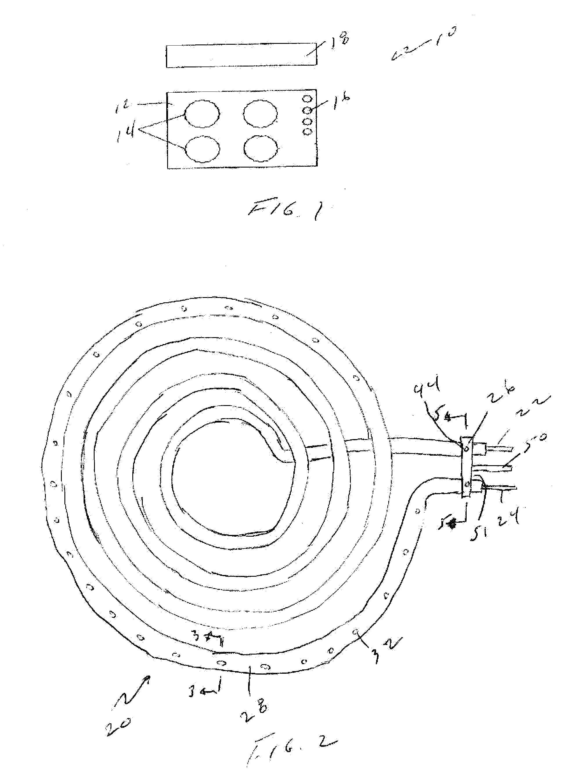
[0019] Referring first to FIG. 1, a preferred embodiment of the fire suppression system of the invention may be retrofit into an existing stove or incorporated in a new stove. An exemplary stove generally identified by the reference numeral 10 includes a stovetop 12, burners 14 and other components, such as control knobs 16. A vent hood 18 is typically mounted above the stovetop 12.

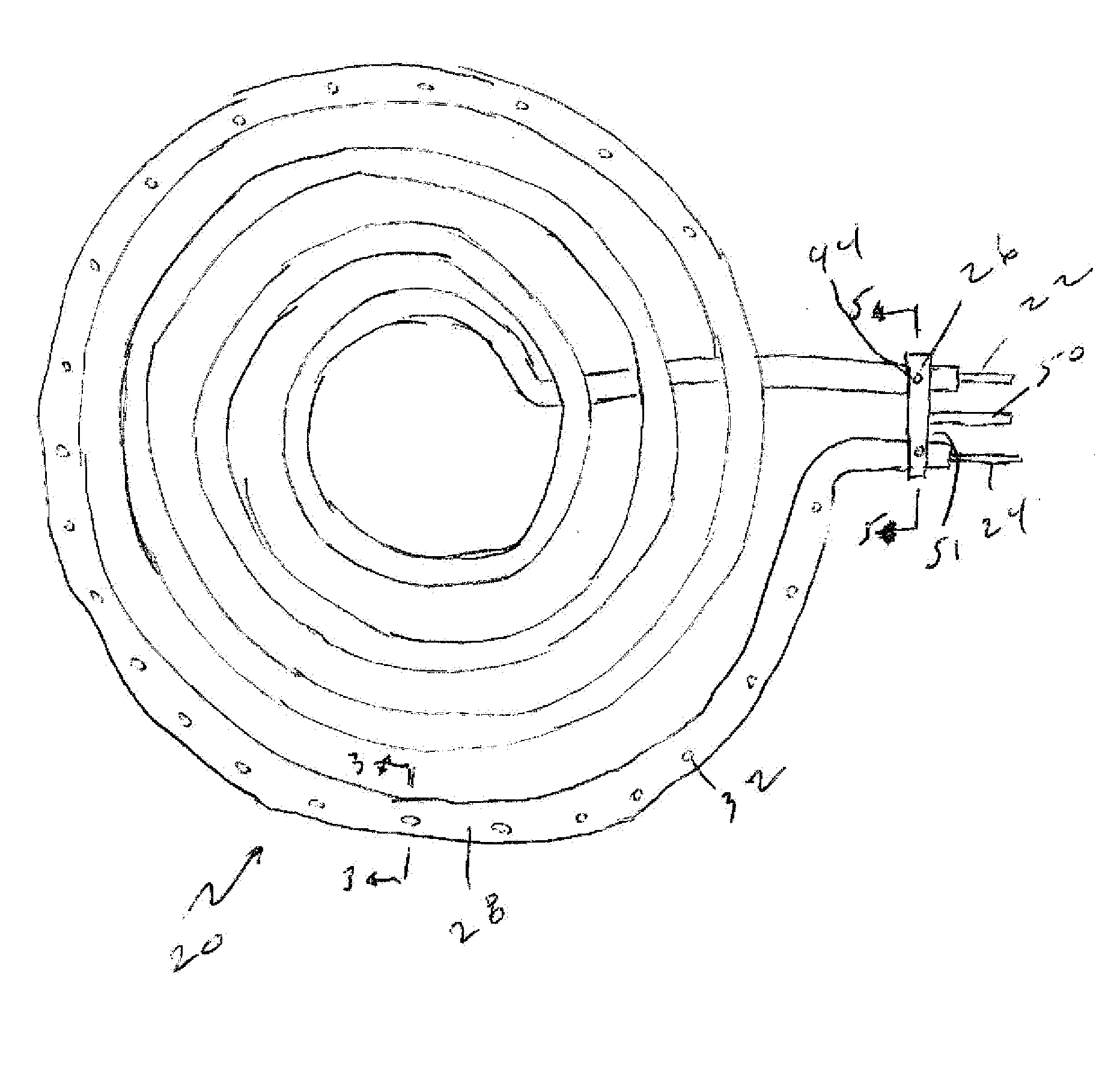
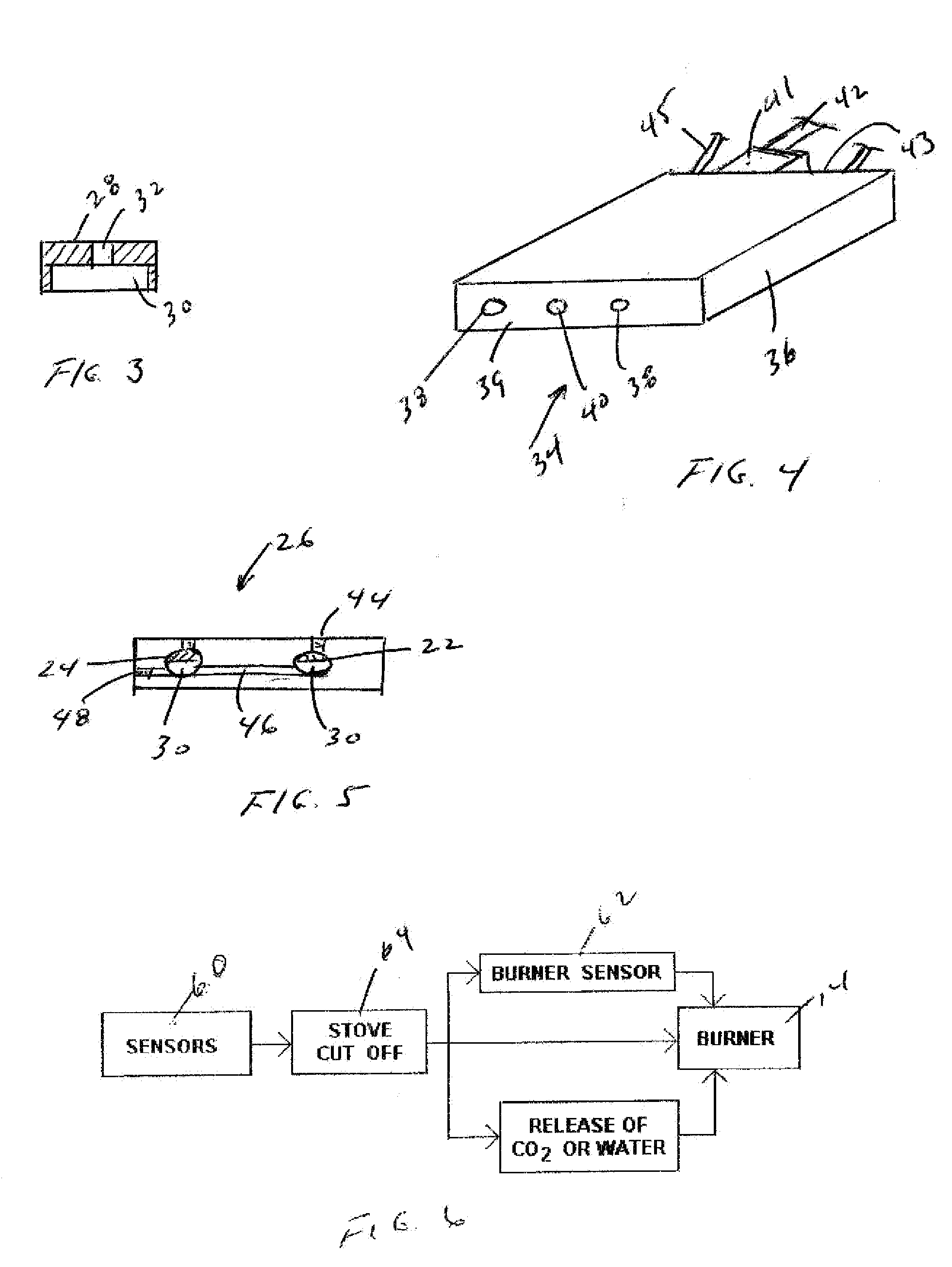
[0020] Referring now to FIG. 2, the burners 14 of the present invention include an electric heating element 20. It is understood, however, that the burners 14 may be gas or electric. The heating element 20 comprises an elongated coiled body terminating at ends 22 and 24. The ends 22 and 24 of the heating element 20 are substantially parallel and are retained in spaced relationship by a spacer bracket 26 secured proximate the ends 22 and 24. The heating element 20 includes a substantially planar top surface 28 defining a substantially flat heating surface. A channel 30, as best shown in FIG. 3, is formed ...


PUM


Abstract

An improved fire extinguishing system for residential and commercial cook stoves and ranges includes one or more heat and/or smoke sensors connected to a control circuit. A cut-off switch activated by the heat and/or smoke sensors is provided to interrupt the flow of gas or electric power to the cook stove burners. The burners are in fluid communication with a source of a fire suppressant. Upon sensing a fire on the cook stove, fluid communication is established between the burners and fire suppressant for rapidly cooling the burners and extinguishing the fire.

Description

BACKGROUND OF THE INVENTION [0001] The present invention relates to a fire suppression system for a stove or cooktop. More particularly, this invention relates to an automatically actuated fire suppression system and method for extinguishing a fire and rapidly cooling a stovetop burner by dispensing a fire suppressant and coolant on the burner and the cookware thereon, such as pot, skillet, or the like. [0002] Many residential and commercial fires originate in the kitchen. Overheated greases or oils during cooking can easily ignite resulting in a potentially dangerous fire, particularly if the pot or skillet on the cook stove is not being attended. Exhaust hoods are commonly installed above stoves. The exhaust hoods typically include a fan and some are equipped with fire suppression equipment. [0003] These fire extinguishing systems however have disadvantages. In those systems where the fire suppression equipment is mounted in the exhause hood, the fire suppression material is relea...

Claims


Application Information

Patent Timeline
Patent Type & Authority Applications(United States)
IPC IPC(8): A62C3/00
CPCF23Q25/00A62C3/006
Inventor HOWETH, JO ANN P.MYERS, WALTER T. SR.
Owner HOWETH JO ANN P
Why Eureka
Try Eureka