Automated transmission controller and vehicle including the automated transmission controller

a transmission controller and automatic technology, applied in the direction of interlocking clutches, cycles, gearing, etc., can solve the problems the method of cycling the shift actuator cannot solve the problem of a dog contact condition, and the cost of cyclic loading

Active Publication Date: 2007-10-18
YAMAHA MOTOR CO LTD
View PDF14 Cites 15 Cited by
  • Summary
  • Abstract
  • Description
  • Claims
  • Application Information

AI Technical Summary

Benefits of technology

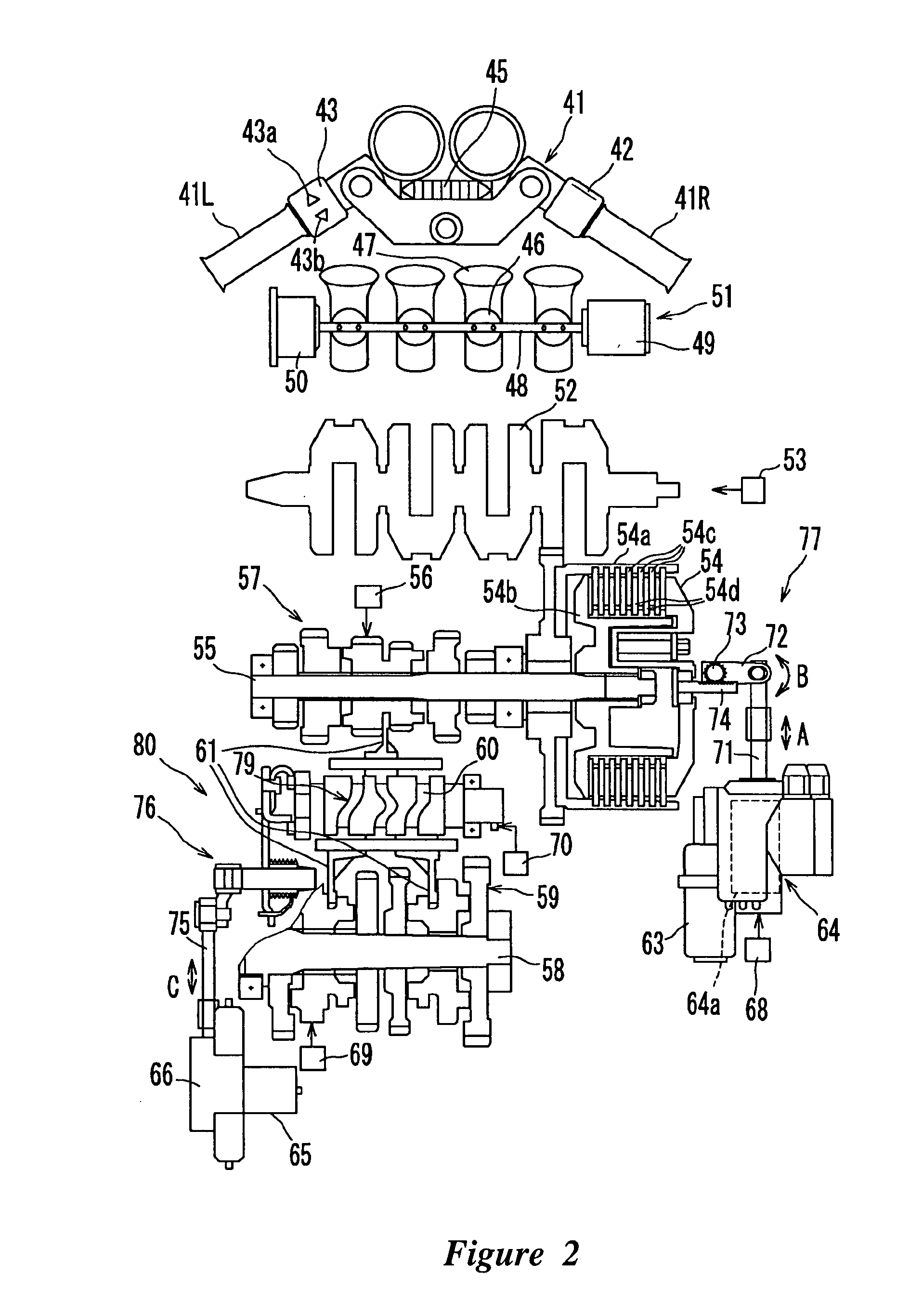
[0008]Thus, in accordance with an embodiment, an automated transmission controller can comprise a friction clutch and a dog-clutch-type transmission having a plurality of first gears on which engaging projections are formed and a plurality of second gears on which engaging concaves engaging with the engaging projections are formed, the engaging projections of the first gears engaging with the corresponding engaging concaves of the second gears to effect a change in gear ratios in the dog-clutch-type transmission. The controller can also include an automated transmission unit having an electrically powered actuator configured to conduct connection and disconnection of the friction clutch, the automated transmission unit also being configured to conduct gear ratio changes of the dog-clutch-type transmission. A control unit can be configured to control the operation of the actuator, and a gear position sensor can be configured to detect the gear position of the dog-clutch-type transmission. The control unit can be configured to perform gear change assist control under which, at the time of shift change, the clutch position of the friction clutch is shifted to the connection side at a connection speed lower than a connection speed until the clutch position reaches a reference clutch position which is located on the disconnection side from a first clutch position where the half-clutch condition ends and on the connection side from a second clutch position where the friction clutch is in the largest possible disconnection condition for its structure, during a period from the time when the clutch position reaches the reference clutch position until the time when engagement condition between the engaging projections and the engaging concaves is detected by the gear position sensor.
[0009]In accordance with another embodiment, an automated transmission controller can comprise a friction clutch and a dog-clutch-type transmission having a plurality of first gears on which engaging projections are formed and a plurality of second gears on which engaging concaves engaging with the engaging projections are formed, the engaging projections of the first gears engaging with the corresponding engaging concaves of the second gears to effect a gear change of the dog-clutch-type transmission. An automated transmission unit can have an electrically powered actuator and configured to conduct connection and disconnection of the friction clutch, the automated transmission unit also being configured to conduct gear ratio changes of the dog-clutch-type transmission. A control unit can be configured to control the operation of the actuator and a main shaft revolution sensor can be configured to detect the revolution of a main shaft connected with the follower side of the friction clutch. The control unit can be configured to perform gear change assist control under which, at the time of gear shift, the clutch position of the friction clutch is shifted to the connection side at a connection speed lower than a connection speed until the clutch position reaches a reference clutch position which is located on the disconnection side from a first clutch position where the half-clutch condition ends and on the connection side from a second clutch position where the friction clutch is in the largest possible disconnection condition for its structure, during a period from the time when the clutch position reaches the reference clutch position until the time when the revolution of the main shaft detected by the main shaft revolution sensor reaches a predetermined value.
[0010]In accordance with yet another embodiment, an automated transmission controller can comprise a friction clutch and a dog-clutch-type transmission having a plurality of first gears on which engaging projections are formed and a plurality of second gears on which engaging concaves engaging with the engaging projections are formed, the engaging projections of the first gears engaging with the corresponding engaging concaves of the second gears to effect gear change of the dog-clutch-type transmission. An automated transmission unit can have an electrically powered actuator and being configured to conduct connection and disconnection of the friction clutch, the automated transmission unit also being configured to conduct gear ratio changes of the dog-clutch-type transmission. A control unit can be configured to control the operation of the actuator and a main shaft revolution sensor can be configured to detect revolution of a main shaft connected with the follower side of the friction clutch. A drive shaft revolution sensor can be configured to detect revolution of a drive shaft connected with the main shaft via the dog-clutch-type transmission. The control unit can be configured to perform gear change assist control under which, at the time of shift change, the clutch position of the friction clutch is shifted to the connection side at a connection speed lower than a connection speed until the clutch position reaches a reference clutch position which is located on the disconnection side from a first clutch position where the half-clutch condition ends and on the connection side from a second clutch position where the friction clutch is in the largest possible disconnection condition for its structure, during a period from the time when the clutch position reaches the reference clutch position until the time when the difference between the revolution of the main shaft detected by the main shaft revolution sensor and the revolution of the drive shaft detected by the drive shaft revolution sensor reaches a predetermined value.

Problems solved by technology

Additionally, such a shift actuator would normally be designed to be more robust and thus more expensive to withstand the cyclic loading.
Finally, the method of cycling the shift actuator cannot solve the problem of a dog contact condition when both the main shaft and the drive shaft are stopped, for example, when the associated vehicle is stopped.

Method used


Image

  • Automated transmission controller and vehicle including the automated transmission controller
  • Automated transmission controller and vehicle including the automated transmission controller
  • Automated transmission controller and vehicle including the automated transmission controller

Examples


second embodiment

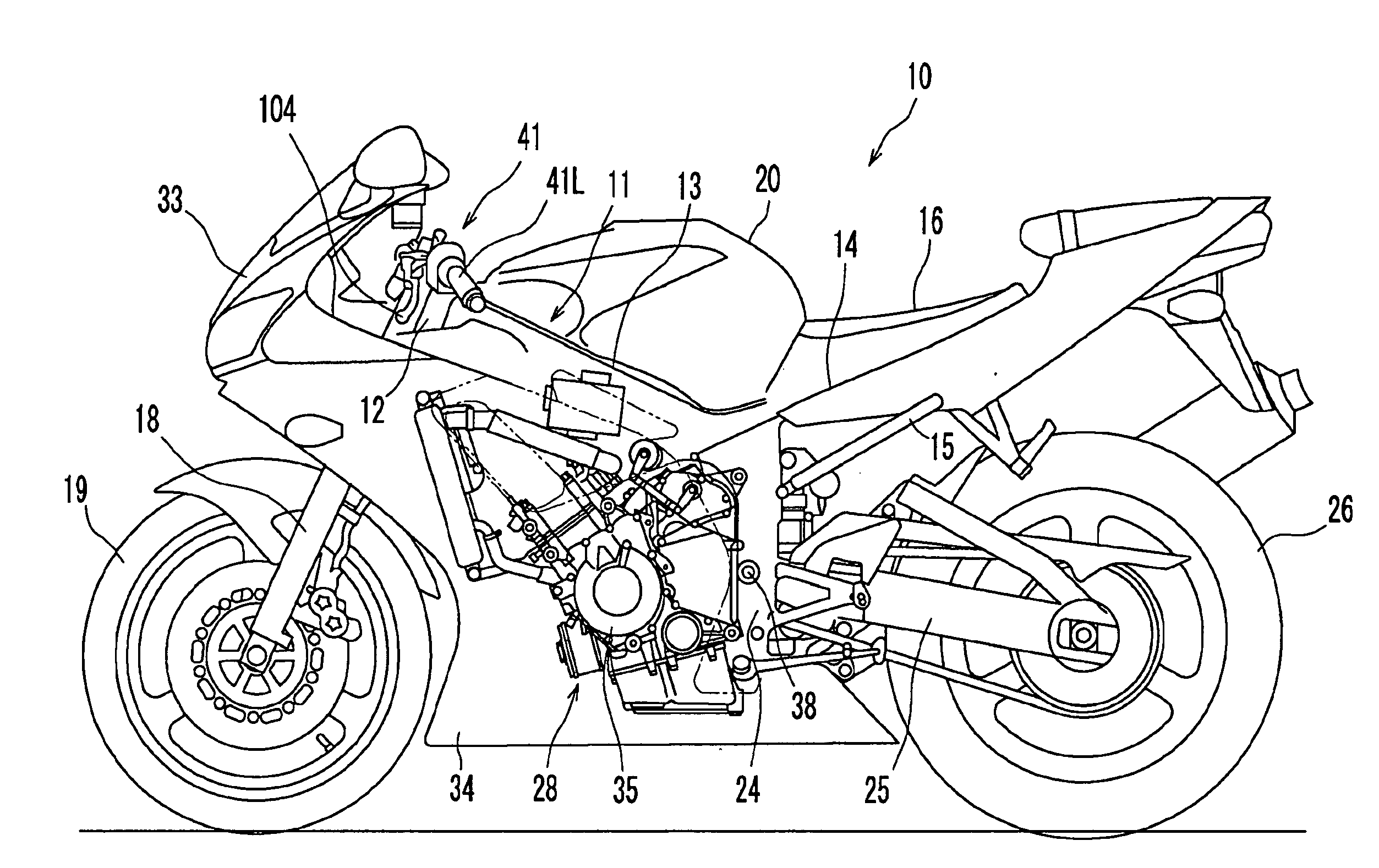
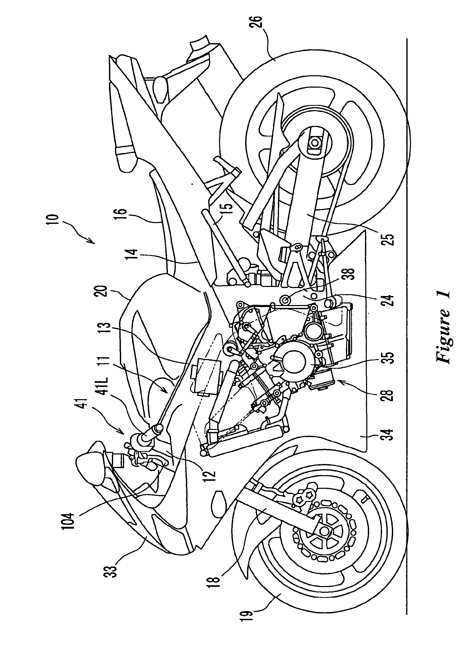
[0087]According to the first embodiment, the low-speed connection of the clutch 54 is ended on the occasion when completion of gear change is detected by the gear position sensor 70. In a second embodiment, however, the low-speed connection of the clutch 54 is ended on the occasion when the revolution of the main shaft 55 detected by the main shaft revolution sensor 56 reaches a predetermined value.

[0088]FIG. 9 is a flowchart showing a shift change control process during stop of a motorcycle, such as the motorcycle 10, in the second embodiment. According to the gear shift control process during stop of the vehicle shown in FIG. 9, step S230 is executed in lieu of step S130 in the gear shift control process during stop of the vehicle shown in FIG. 7. In step S230, the ECU 100 can determine whether the revolution of the main shaft has reached a predetermined value. That is, the ECU 100 judges whether the revolution of the main shaft 55 detected by the main shaft revolution sensor 56 h...

third embodiment

[0092]According to the following third embodiment, the low-speed connection of the clutch 54 is ended on the occasion when the difference between the revolution of the main shaft 55 detected by the main shaft revolution sensor 56 and the revolution of the drive shaft 58 detected by the vehicle speed sensor 69 reaches a predetermined value.

[0093]FIG. 10 is a flowchart showing a gear shift control process during stop of a motorcycle, such as the motorcycle 10, in the third embodiment. According to the gear shift control process during stop of the vehicle shown in FIG. 10, step S330 is executed in lieu of step S130 in the shift change control process during stop of the vehicle shown in FIG. 7. In step S330, the ECU 100 can determine whether the revolutions of the main shaft 55 and the drive shaft 58 have reached a predetermined value. That is, the ECU 100 can judge whether the difference between the revolution of the main shaft 55 detected by the main shaft revolution sensor 56 and the...

fourth embodiment

[0096]FIGS. 11(a) and 11(b) show the clutch position with elapse of time when a gear shift control process is conducted during stop of a motorcycle, such as the motorcycle 10 according to a fourth embodiment. According to the motorcycle 10 in the fourth embodiment shown in FIGS. 11(a) and 11(b), the clutch 54 is connected until the clutch position reaches the reference clutch position, and thereafter the low-speed connection and disconnection of the clutch 54 are repeated. When completion of gear change is detected by the gear position sensor 70 during the low-speed connection and disconnection of the clutch 54 is repeated, the clutch disconnection step is initiated. The control of repeating the low-speed connection of the clutch 54 shown in FIGS. 11(a) and 11(b) also corresponds to the gear change assist control according to the invention.

[0097]As described above, according to the motorcycle in the above embodiments, the clutch position of the clutch 54 reaches the dog-contact canc...


PUM


Abstract

Rotational driving force can be transferred to the follower side (clutch plate) of a friction clutch by adjusting the engagement condition of the clutch so that a first gear and a second gear of a dog-clutch-type transmission can rotate relative to each other. At the time of shift change during stop of the vehicle, the clutch can be further connected at a low speed after connection of the clutch until it reaches a reference clutch position.

Description

CROSS-REFERENCE TO RELATED APPLICATIONS[0001]This application claims the priority benefit of Japanese Patent Application No. 2006-114701, which was filed on Apr. 18, 2006 and which is hereby incorporated by reference in its entirety.BACKGROUND OF THE INVENTIONS[0002]1. Field of the Inventions[0003]The present inventions relate to an automated transmission controller which can automatically execute shift changes, and to a vehicle including such as automated transmission controller.[0004]2. Description of the Related Art[0005]Recently, vehicles with electronically actuated manual transmissions have become commercially available. These transmissions are largely the same as any conventional manual transmission, except electronic actuators have been added to allow the otherwise manual transmission to be operated electronically.[0006]The actuators are used to automate certain operations so that the system can automate a series of start, stop and shift change operations (clutch disengageme...

Claims


Application Information

Patent Timeline
Patent Type & Authority Applications(United States)
IPC IPC(8): B60W10/10F16D25/08F16D48/02
CPCB60W10/02B60W10/11B60W30/19B60Y2200/12Y10T74/19284F16H61/682F16H63/18F16H2061/047F16H2061/0474F16H61/0437
Inventor MINAMI, KENGO
Owner YAMAHA MOTOR CO LTD
Why Eureka
Try Eureka