Imaging device and autofocusing method

a technology of imaging device and autofocusing method, which is applied in the direction of focusing aids, instruments, television systems, etc., can solve the problems of difficult to accurately detect the hill-climbing direction, and reduce the reliability of the af evaluation value, so as to effectively control the potential effect of magnification chang

Inactive Publication Date: 2008-07-10
ELMO CO LTD
View PDF3 Cites 23 Cited by
  • Summary
  • Abstract
  • Description
  • Claims
  • Application Information

AI Technical Summary

Benefits of technology

[0010]The imaging device according to this aspect of the invention sets the variation range of changing the state of the optical system for detection of the focusing direction, based on at least the information on the magnification change of the optical image due to the change of the state of the optical system. The imaging device detects the variation in intensity of the specific signal, while changing the state of the optical system in the set variation range. The imaging devi

Problems solved by technology

This makes it difficult to accurately detect the hill-climbing direction.
This lowers the reliability of the AF evaluation value and thus makes it difficult to accurately detect the hill-climbing direction.
The unlimited incr

Method used


Image

  • Imaging device and autofocusing method
  • Imaging device and autofocusing method
  • Imaging device and autofocusing method

Examples


Embodiment Construction

[0022]One mode of carrying out the invention is described below in the following sequence with reference to the accompanied drawings:

[0023](1) General Structure of Digital Video Camera

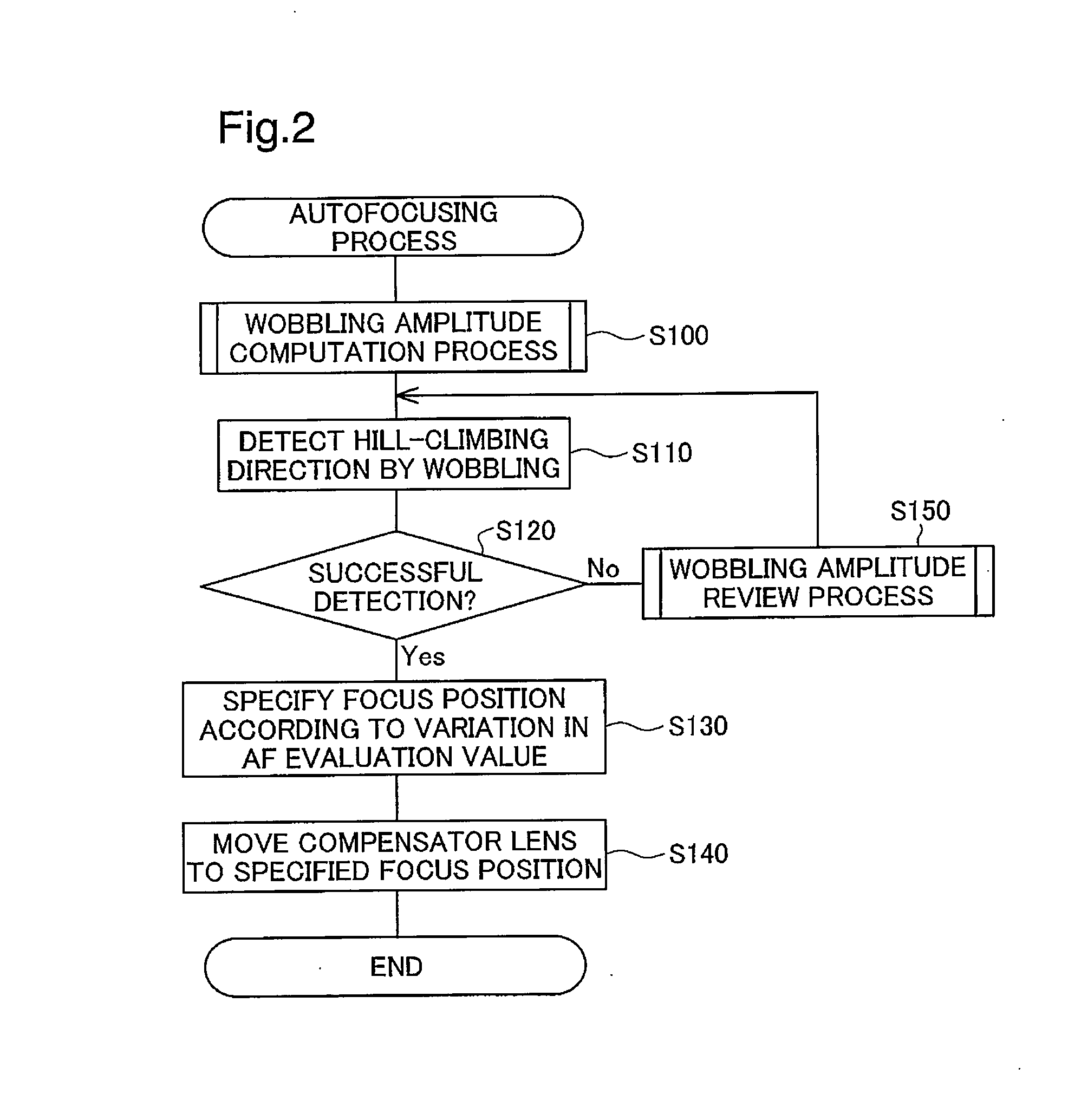
[0024](2) Autofocusing Process

[0025](3) Wobbling Amplitude Computation Process

[0026](4) Wobbling Amplitude Review Process

[0027](5) Other Aspects

[0028](1) General Structure of Digital Video Camera

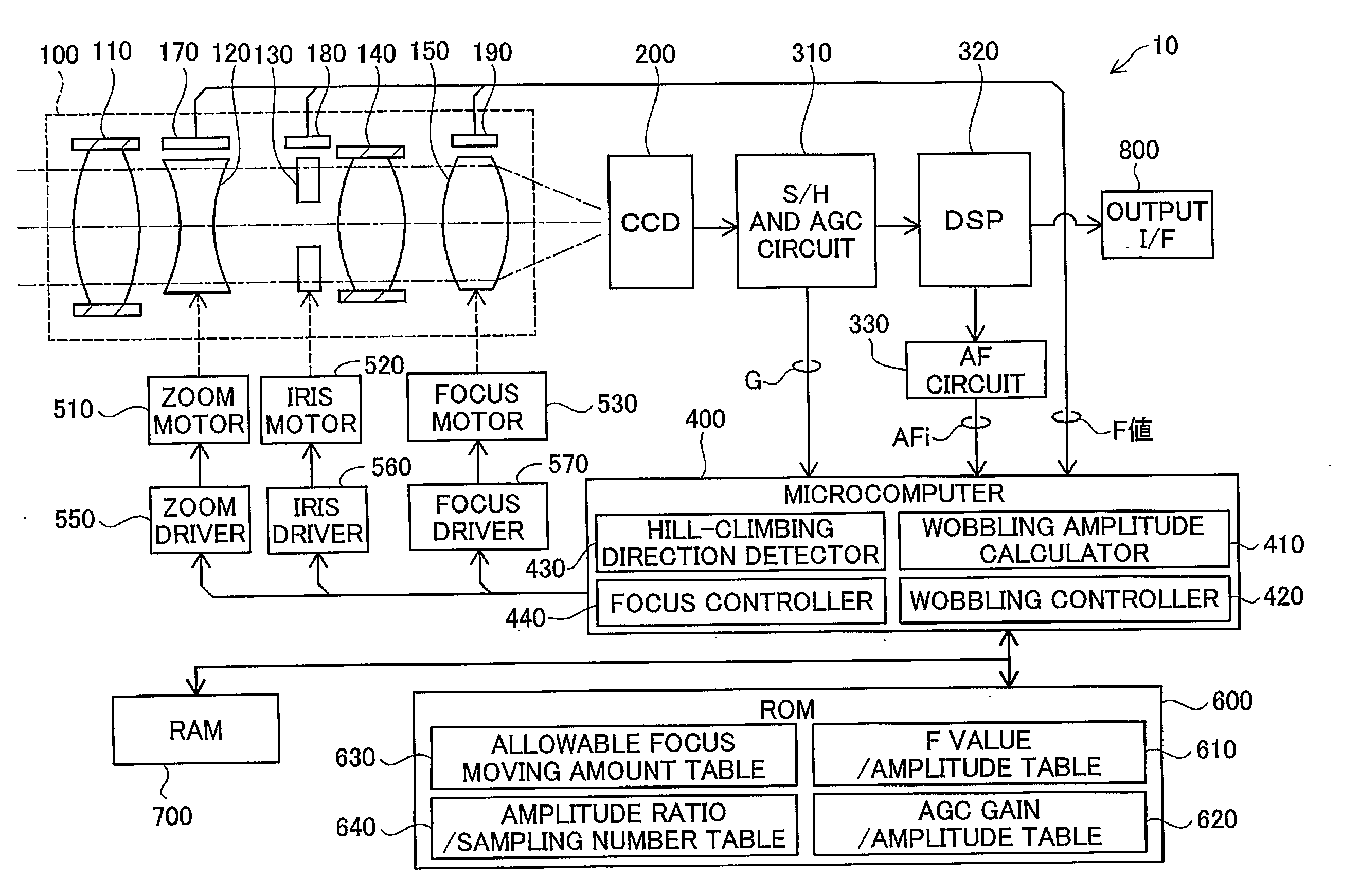
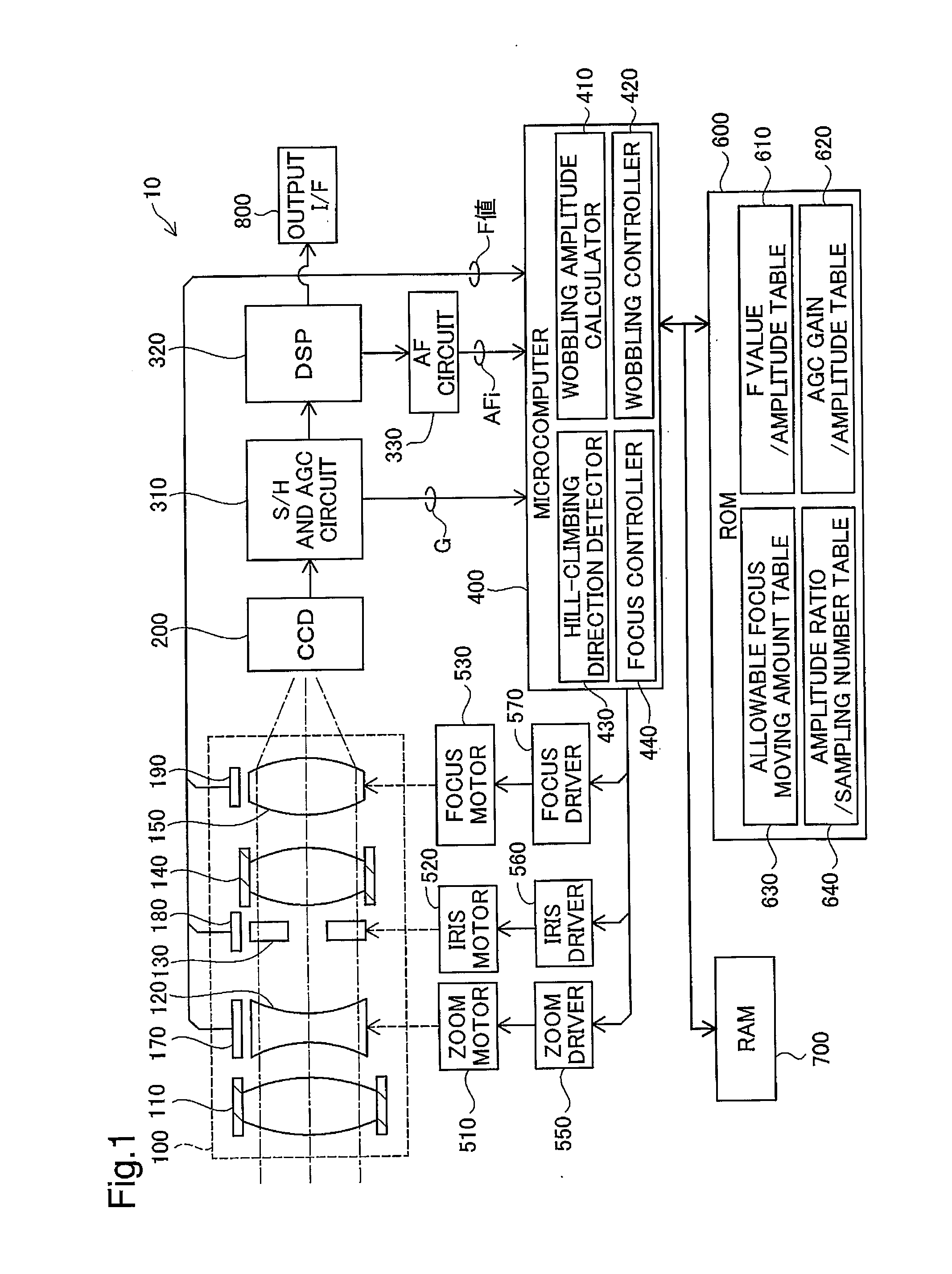
[0029]FIG. 1 is a block diagram illustrating the schematic structure of a digital video camera 10 in one embodiment of the invention. The digital video camera 10 is a fixed security camera having hill-climbing autofocus functions. As illustrated in FIG. 1, the digital video camera 10 includes a lens block 100, a CCD 200, a sample hold (S / H) and AGC (automatic gain control) circuit 310, a DSP (digital signal processor) 320, an AF circuit 330, a microcomputer 400, lens and iris drive motors 510 to 530, lens and iris drivers 550 to 570, a ROM 600, a RAM 700, and an output interface 800.

[0030]The lens block 100 inc...


PUM


Abstract

In an imaging device according to one aspect of the invention, an amplitude demand Ac is specified according to a wobbling amplitude Ai required for detection of a hill-climbing direction based on an F value and a wobbling amplitude Ag required for detection of the hill-climbing direction based on an AGC gain. An allowable amplitude Am set for preventing a potential image shake caused by a magnification change with a position shift of a compensator lens in wobbling is specified corresponding to a zoom position and an object distance. When Ac>Am, the control procedure restricts the wobbling amplitude to Am and increases a sampling number of AF evaluation values to be detected at respective positions in wobbling, in order to ensure the sufficient detection performance of the hill-climbing direction. When Ac□Am on the other hand, the control procedure sets Ac to the wobbling amplitude. This arrangement of the imaging device efficiently ensures the sufficient detection performance of the hill-climbing direction for autofocusing control, while effectively preventing deterioration of the quality of a captured image due to the magnification change in the wobbling motion.

Description

CLAIM OF PRIORITY[0001]The present application claims the priority from Japanese application P2007-1109A filed on Jan. 9, 2007, the contents of which are hereby incorporated by reference into this application.BACKGROUND[0002]1. Field of the Invention[0003]The present invention relates to an autofocusing technique for an imaging device that converts an optical image, which is captured via an optical system having a focus adjustable function, into a video signal by means of an imaging system.[0004]2. Description of the Related Art[0005]The advance of the digital techniques has boosted the spread of digital video cameras and other imaging devices. The imaging device generally has an autofocusing mechanism that automatically adjusts the position of a focus lens to be focused on a subject. One typical technique adopted for the autofocusing mechanism is hill-climbing control. The hill-climbing control adopts the wobbling technique to identify the focusing direction of a focus lens on a su...

Claims


Application Information

Patent Timeline
IPC IPC(8): H04N5/232
CPCG02B7/023G02B7/102H04N5/23212G03B13/36G02B7/282H04N23/673
Inventor TOGUCHI, MASAAKI
Owner ELMO CO LTD
Why Eureka
Try Eureka