Automated dispenser

Inactive Publication Date: 2007-10-18
KENNEY JAMES W
View PDF25 Cites 13 Cited by
  • Summary
  • Abstract
  • Description
  • Claims
  • Application Information

AI Technical Summary

Benefits of technology

[0006] The present invention meets the need in the art for an improved automated paper dispenser. In one embodiment, basic elements of the invention comprise two drive roller pairs: an infeed roller pair and a delivery roller pair. The roller pairs are sized in length to accommodate the width of the supply paper roll. As will be more fully described below, a length of paper web is initially advanced through both roller pairs at the same speed. When the desired length has been observed, the infeed rollers are disengaged from the drive mechanism and braked. The slowed infeed rollers apply a drag force on the paper supply roll sufficient to create tension in the web between the braked infeed rollers and the delivery rol

Problems solved by technology

The problem with the Gergek device, however, is presented by

Method used


Image

  • Automated dispenser
  • Automated dispenser
  • Automated dispenser

Examples


Embodiment Construction

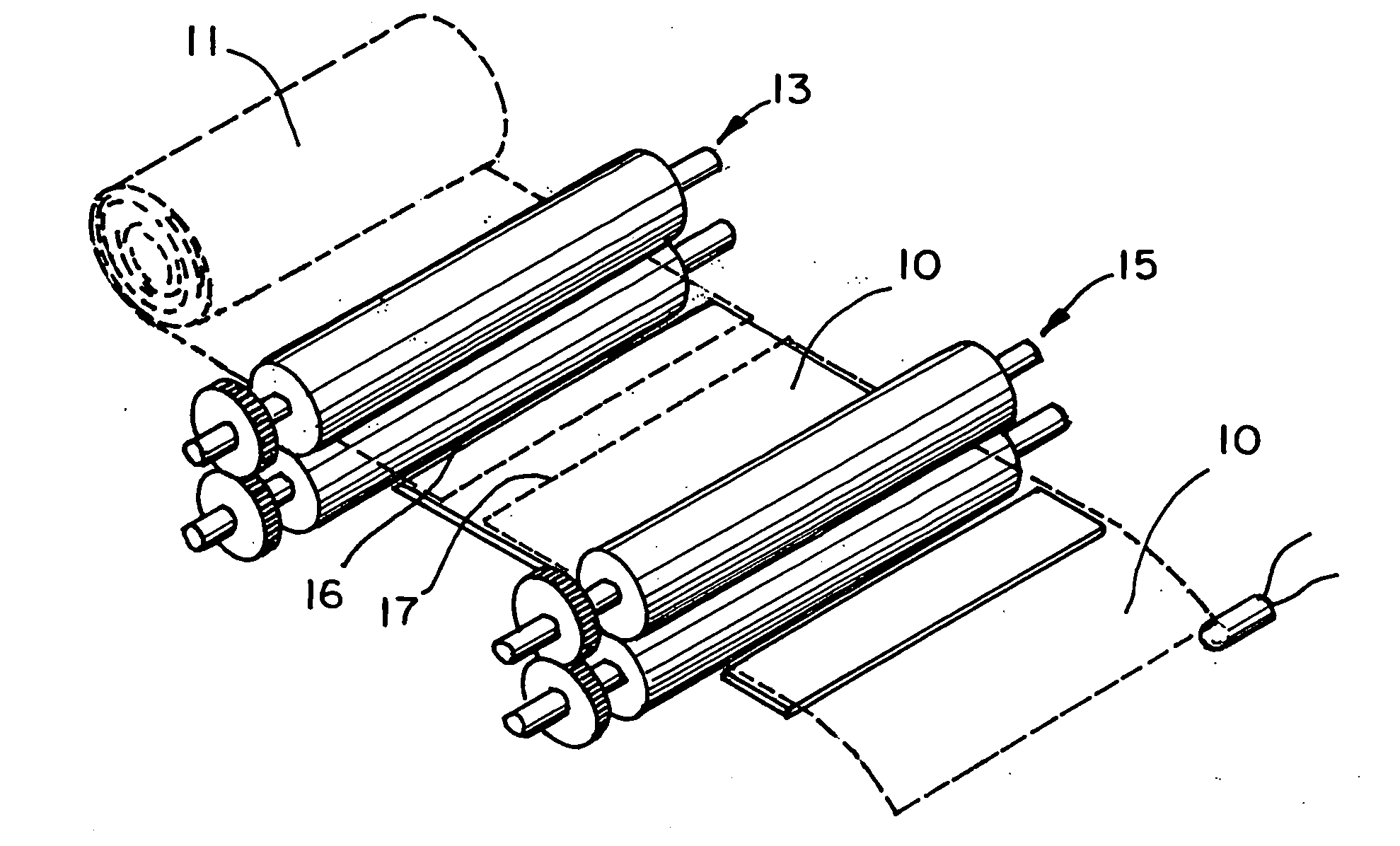
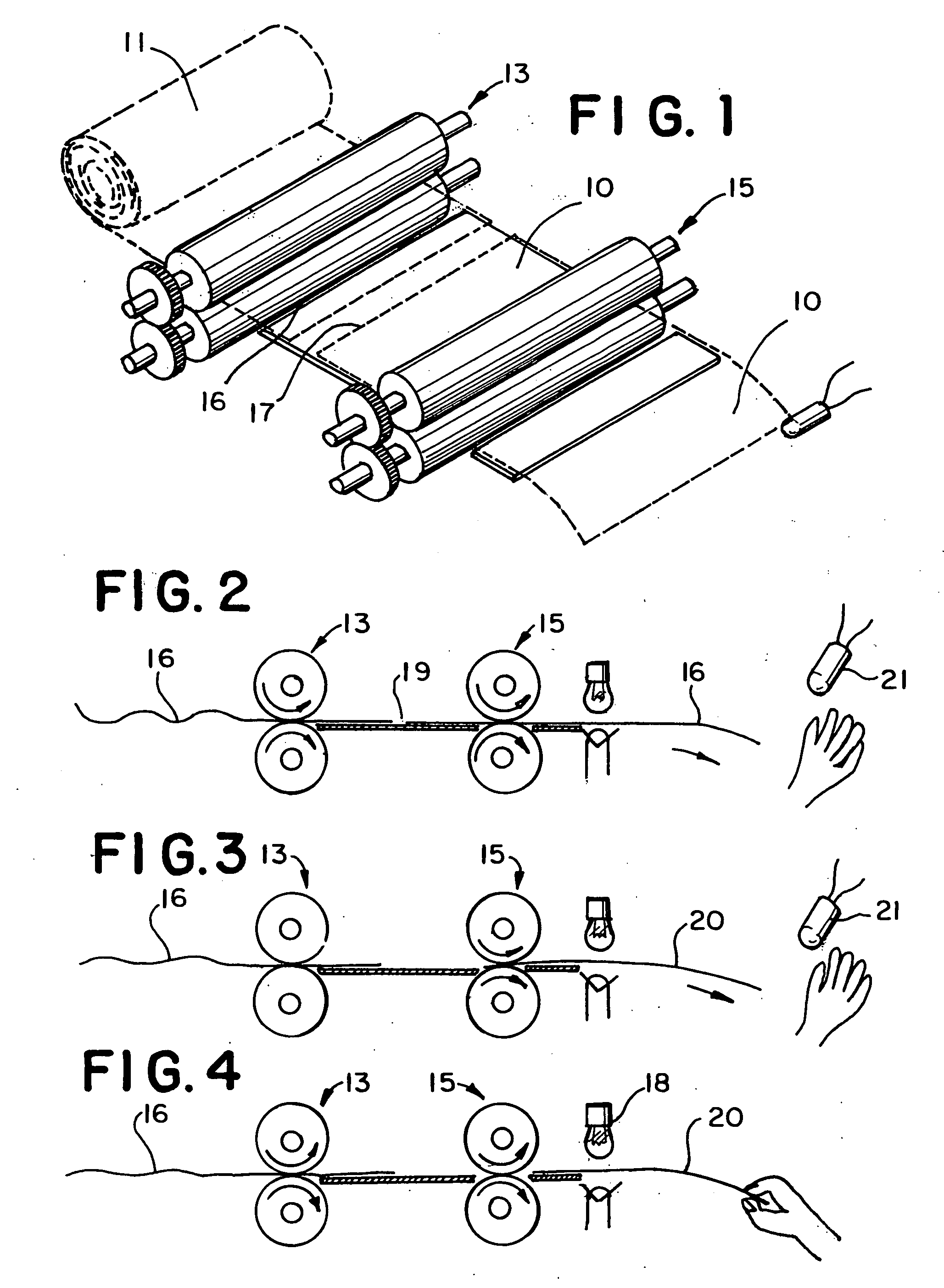
[0023] Referring now to FIG. 1, the basic drive elements which feed and dispense individual sheets of paper 10 from roll 11 include a first infeed roller pair 13 and a second delivery roller pair 15. Each roller pair includes driveshafts which are geared together to provide a nip therebetween which propels the web 16 in a direction of advancement, or in the case of roller pair 13, alternatively retards the advancement of the web to provide a tearing force to a line of perforation 17 in the web at a point in the web path between the roller pairs. The web includes lateral spaced lines of perforation to provide areas of weakness where tearing of the web can more easily occur.

[0024] Referring now to FIGS. 2, 3, and 4, movement along the web path is diagrammatically shown in three stages. In FIG. 2, the dispensing action has been initiated by the operator's hand coming into proximity with sensor 21. At the desired point when a sufficient length of web 16 has been dispensed, a braking me...


PUM


Abstract

A device for dispensing a rolled web of material having a plurality of laterally-extending, longitudinally-spaced lines of perforation. The device has a frame for supporting the rolled web such that lengths of the web are removed from the roll in a direction of advancement as the roll rotates. An infeed roller pair is rotatably mounted on the frame. The infeed roller pair provides a nip therebetween for receiving the web from the roll and for moving it forward in the direction of advancement. A pair of delivery rollers is rotatably mounted on the frame in spaced relation with the first pair of rollers. The second pair of rollers receives the web from the first roller pair and provides a nip therebetween for moving the web in the direction of advancement. Motor means drives the infeed roller pair and the delivery roller pair. Brake means is affixed to the infeed roller pair for slowing the rotational speed thereof relative to the delivery roller pair whereby sufficient tension is created in a length of web located between said roller pairs to tear the web across one of the lines of perforation. Actuation means selectively actuates the brake means during advancement of the web by the delivery rollers.

Description

FIELD OF THE INVENTION [0001] The present invention relates to a dispensing system for a continuous web of material. More specifically, it relates to a paper towel dispenser for a continuous roll of perforated paper that permits any length equal to a multiple of unit lengths between roll perforations to be selectively dispensed. BACKGROUND OF THE INVENTION [0002] The most commonly used paper dispenser found in the home is a simple toilet paper bar and / or a two sided paper towel bracket. To dispense the paper, the user pulls on the paper until he or she dispenses the desired amount and then rapidly jerks and tears the paper at the next perforation. [0003] Motorized paper towel dispensers are commonly found in commercial environments. Motorized dispensers usually hold a large roll of non-perforated paper supplied by commercial vendors. Some of these motorized dispensers dispense paper when they detect motion or the presence of a hand. Most automated machines dispense only a pre-determ...

Claims


Application Information

Patent Timeline
IPC IPC(8): B26F3/00
CPCB26F3/002A47K10/36A47K10/3612A47K2010/3668Y10T225/35
Inventor KENNEY, JAMES W.
Owner KENNEY JAMES W
Why Eureka
Try Eureka