Medical image display apparatus

a medical image and display device technology, applied in the field of medical image display devices, can solve the problems of reducing the size of the displayed medical image, unable to observe parts of the image, and more difficult to observe the details of the medical image or the like, so as to achieve the effect of not becoming complicated

Active Publication Date: 2007-10-18
TOSHIBA MEDICAL SYST CORP
View PDF18 Cites 84 Cited by
  • Summary
  • Abstract
  • Description
  • Claims
  • Application Information

AI Technical Summary

Benefits of technology

[0021]According to the second embodiment, simply specifying a medical image and an image display region enables execution of the processing that was conventionally executed by operation of the software keys. Therefore, there is no need to display software keys for execution of processing on the medical image display screen. As a result, it is possible to solve the disadvantages resulting from the software keys being displayed on the medical image display screen. In addition, because performing only the simple operation of specifying a medical image enables execution of the desired processing, operationality does not become complicated.

Problems solved by technology

Therefore, a disadvantage has occurred wherein, when displaying a medical image with large size on the display screen, the software keys are displayed overlapping the medical image and therefore part of the image cannot be observed.
However, the size of the displayed medical image is reduced, disadvantageously making it more difficult to observe the details of the medical image or the like.
However, the former results in increased cost or the like and the latter causes disadvantages such as complicating the observation work.
Therefore, these remedies are far from an acceptable solution from the viewpoint of the users.
Therefore, a problem occurs in that the operating procedure becomes more complicated compared to the traditional configuration in which only step (2) is performed.

Method used


Image

  • Medical image display apparatus
  • Medical image display apparatus
  • Medical image display apparatus

Examples


example modifications

[0185]The configuration described above in detail is merely one specific example implementation of the medical image display apparatus according to the present invention. Thus, it is possible to accordingly apply any modification within the scope of the present invention. Hereinafter, example modifications related to the above embodiments are described.

first example modification

[0186]The first example modification is an example modification of the approximate section image selection processing. The medical image display apparatus related to this example modification has the similar configuration to the above embodiment (cf. FIG. 1). In this regard, however, the tomographic image generating component 6 in this example modification performs the processing for generating image data of a tomographic image having the cross-sectional position between two tomographic images with different cross-sectional positions. This processing is, in other words, an interpolation. The tomographic image generating component 6 is included in one example of the “interpolated tomographic image generating component” of the present invention.

[0187]It is assumed that the thumbnail displayed on the thumbnail display region P1 and the observation image displayed on the observation image display region P4 are tomographic images of the same cross-sectional direction. Herein, it is assum...

second example modification

[0194]The medical image display apparatus related to the second example modification is intended to improve the efficiency in the entire system as well as the effects of the above embodiment by requesting of an external apparatus (viewer or the like) to execute the predetermined processing.

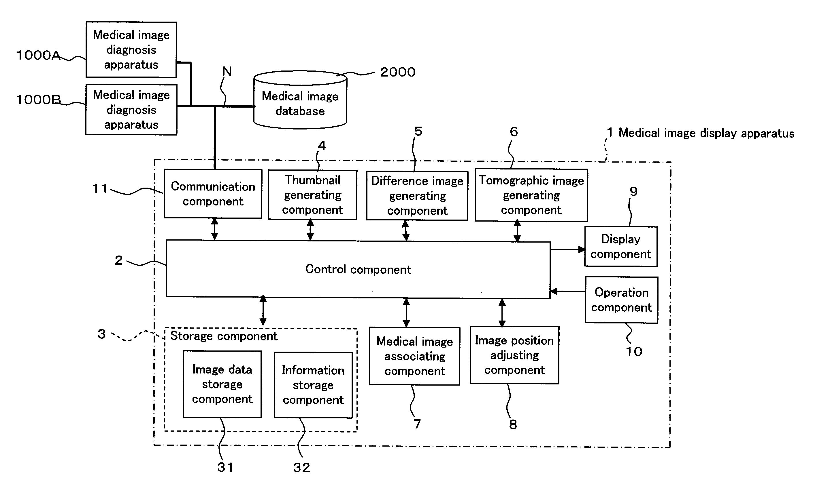
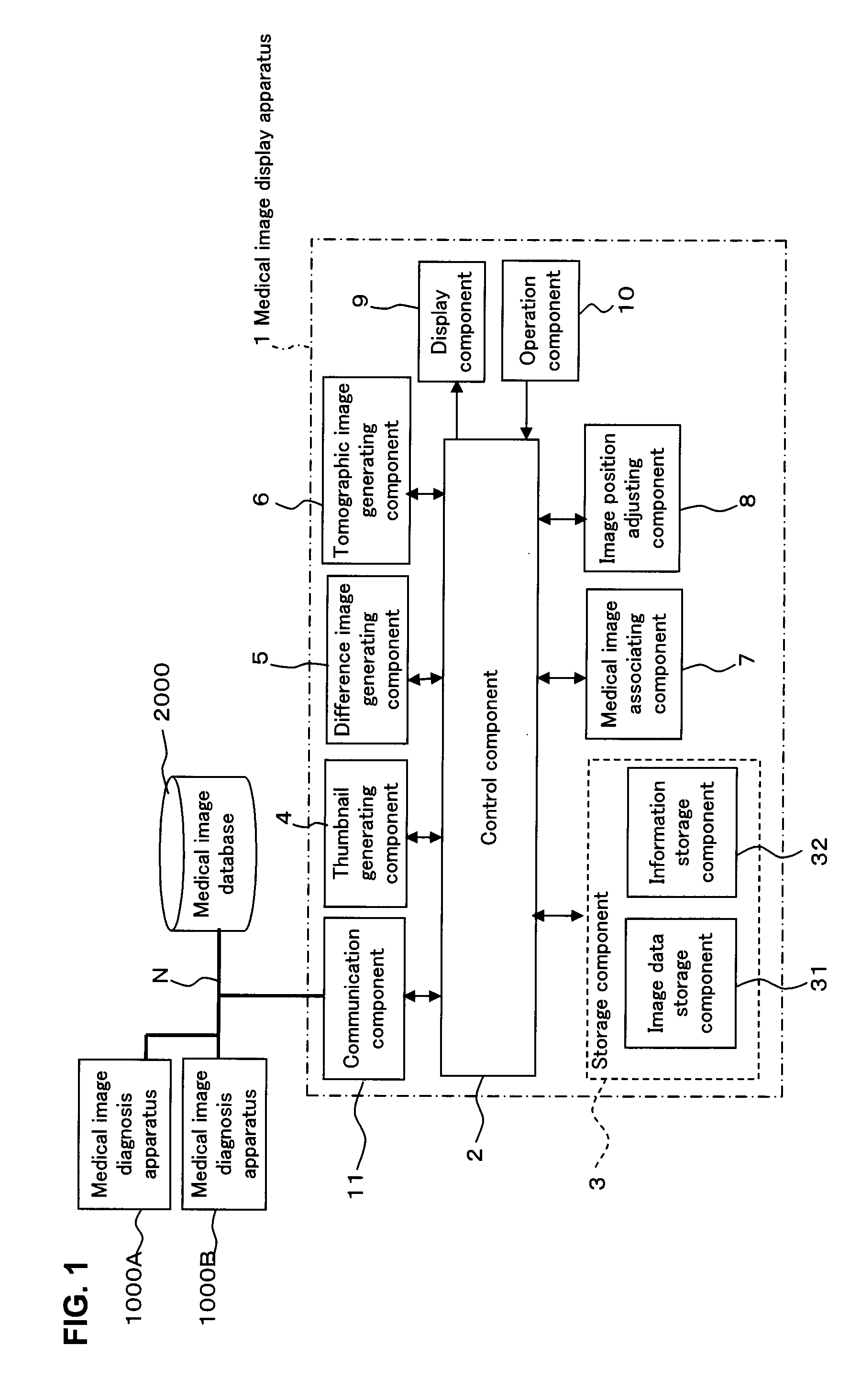
[0195]FIG. 21 shows one example of the medical image display apparatus related to this example modification. The medical image display apparatus 100 shown in FIG. 21 is provided with a control component 2, a storage component 3, a thumbnail generating component 4, a medical image associating component 7, a display component 9, an operation component 10, and a communication component 11 as is in the case with the medical image display apparatus 1 in the above embodiment. The communication component 11 is included in one example of the “communication component” of the present invention. Incidentally, there is no need to be provided with a difference image generating component 5, a tomographic image ...


PUM


Abstract

A medical image display apparatus 1 having a display component 9, an image data storage part 31, an information storage component 32, an operation component 10, and a control part 2. The display component 9 displays a medical image display screen P on which image display regions P1 to P4 are defined. The image data storage part 31 stores image data of medical images. The information storage component 34 stores process associating information 32a for associating combinations of the image display regions P1 to P4 with the processing content of image data of medical images. The control part 2, when two medical images displayed on different image display regions of the image display regions P1 to P4 have each been designated using the operation component 10, instructs to execute, for at least one image data of said two medical images, the process indicated in the processing content associated with the combination of the image display regions in which these two medical images are displayed by the process associating information 32a.

Description

BACKGROUND OF THE INVENTION[0001]1. Field of the Invention[0002]The present invention relates to a medical image display apparatus for conducting interpretation of a medical image obtained by a medical image diagnosis apparatus.[0003]2. Description of the Related Art[0004]Conventional medical image diagnosis apparatuses have been widely used for obtaining medical images. Such medical image diagnosis apparatuses include an X-ray diagnosis apparatus, an X-ray CT apparatus, an MRI apparatus, a nuclear medical diagnosis apparatus (e.g. a positron emission computed tomography apparatus, a single photon emission computed tomography apparatus), and an ultrasound diagnosis apparatus, and so on.[0005]The obtained medical image will be displayed on the medical image display apparatus and provided for interpretation. Incidentally, a system configured to save the obtained medical image in a database and download the desired medical image from the database to the medical image display apparatus ...

Claims


Application Information

Patent Timeline
Patent Type & Authority Applications(United States)
IPC IPC(8): G09G5/00G16H30/20G16H50/20
CPCG06F19/321G06F19/32G06F19/327G06F3/0486G06F3/04845G06F19/3406G06F3/04886G06F19/34G16H50/20G16H30/20G16H30/40G16H40/20G16H40/63
Inventor MATSUE, KENJINIWA, KENICHI
Owner TOSHIBA MEDICAL SYST CORP
Why Eureka
Try Eureka