Transflective LC Display Having Backlight With Spatial Color Separation

a technology of transflective lc display and color separation, applied in non-linear optics, instruments, optics, etc., can solve the problems of limiting the display's ability to present easily viewable images, and reducing the available brightness of both transmissive and reflective operating modes. , to achieve the effect of higher resolution operation and enhanced efficiency

Inactive Publication Date: 2007-10-18
3M INNOVATIVE PROPERTIES CO
View PDF40 Cites 32 Cited by
  • Summary
  • Abstract
  • Description
  • Claims
  • Application Information

AI Technical Summary

Benefits of technology

[0015]Due to the placement of the color filter in relation to the transflector, disclosed LC displays are capable of monochrome operation in reflective mode and full color operation ...

Problems solved by technology

But such intensity modulation cannot produce a range of colors at any arbitrary location on the viewing area.
If such a color filter is used in the LC panel of a transflective display, the high average absorption of the color filter substantially reduces the available brigh...

Method used


Image

  • Transflective LC Display Having Backlight With Spatial Color Separation
  • Transflective LC Display Having Backlight With Spatial Color Separation

Examples


Embodiment Construction

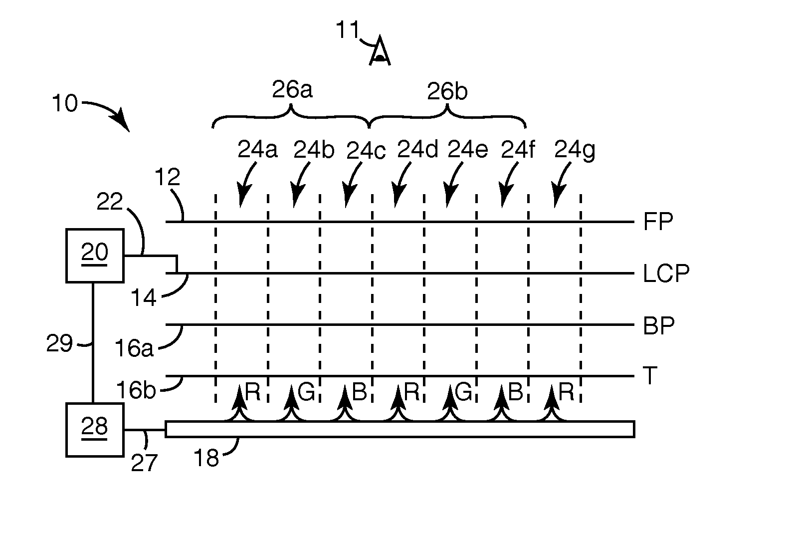
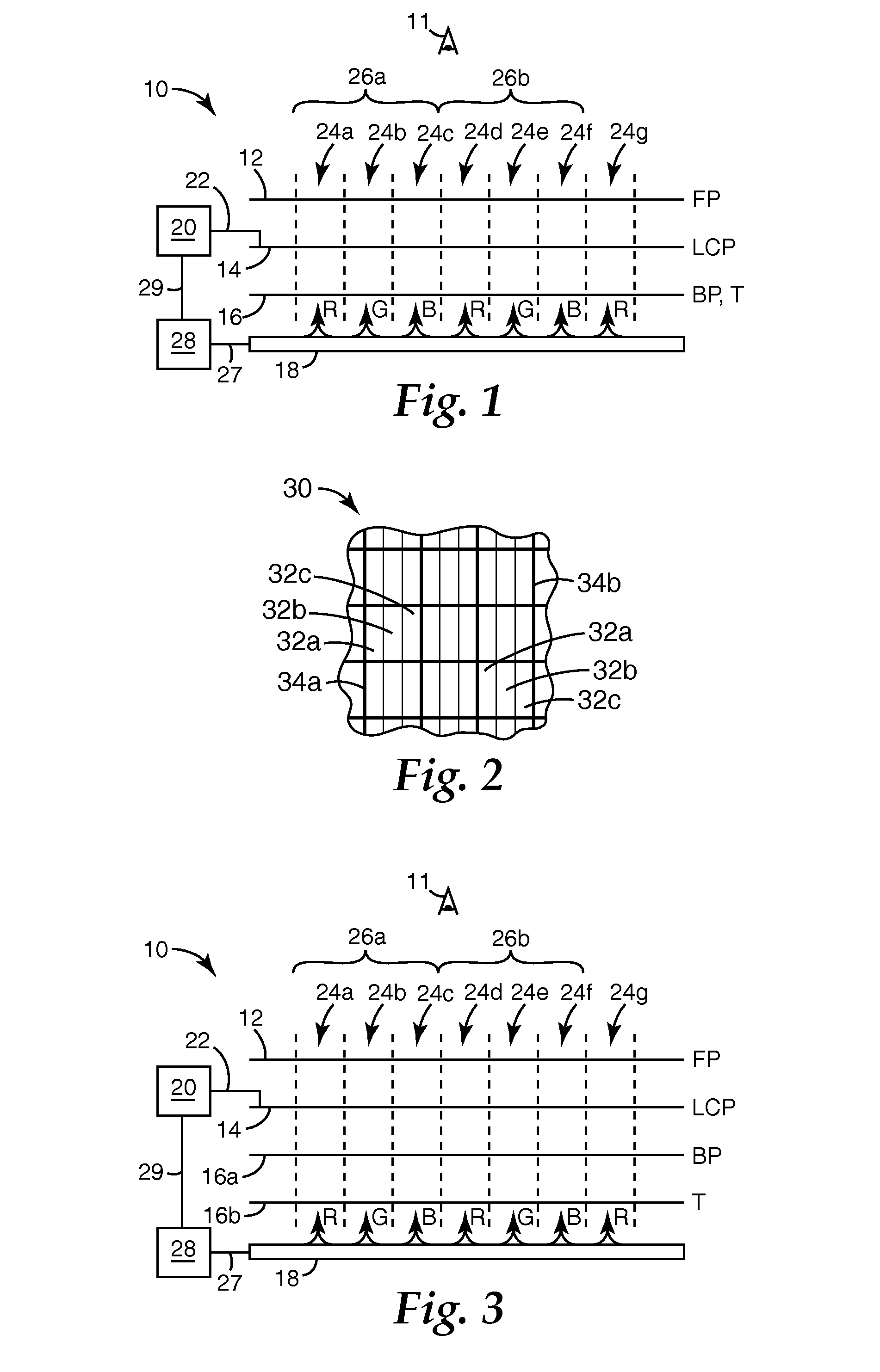
[0021]FIG. 1 shows a schematic side view of a portion of a transflective LC display 10 that includes a front polarizer 12, an LC panel 14, a back polarizer 16, and a backlight 18. A controller 20 is electronically coupled to LC panel 14 via a connection 22 to control the optical state of individual pixels 24a-g of the LC panel, which pixels extend in a repeating pattern or array over an area that defines the overall viewing area of the display.

[0022]Front polarizer 12 can be any known polarizer, but in exemplary embodiments it is an absorptive polarizer (sometimes also referred to as a dichroic polarizer) for ease of viewing and reduced glare for observer 11. Preferably, polarizer 12 is a flexible polymer-based film and is laminated or otherwise adhered to LC panel 14, for example, using an optically clear adhesive. If polarizer 12 is a linear polarizer, it has a pass axis and a block axis in the plane of the film or layer. Light polarized parallel to the pass axis is transmitted, a...


PUM


Abstract

A transflective display includes a liquid crystal (LC) panel having an array of pixels defining a viewing area, the panel being disposed between a front and back polarizer. The display also includes a backlight and a transflector, except that the transflector may optionally be or include the back polarizer. The transflector is disposed between the LC panel and the backlight. The backlight produces multiple light components that are separated spatially over the viewing area to give the display a full color appearance in the transmissive viewing mode. The multiple light components may be, for example, red, green, and blue light components, or another set of light components capable of producing white light. The display can provide a monochrome image in reflection and a full color image in transmission.

Description

CROSS REFERENCE TO RELATED APPLICATIONS[0001]This application claims the benefit under 35 U.S.C. § 119(e) of U.S. Provisional Application 60 / 744,725, filed Apr. 12, 2006.FIELD OF THE INVENTION[0002]The present invention relates to display devices, particularly those that utilize a liquid crystal (LC) panel and that can operate in both reflected ambient light and transmitted light originating from a backlight, and related articles and processes.DISCUSSION[0003]Microprocessor-based devices that include electronic displays for conveying information to a viewer have become nearly ubiquitous. Mobile phones, handheld computers, personal digital assistants (PDAs), electronic games, MP3 players and other portable music players, car stereos and indicators, public displays, automated teller machines, in-store kiosks, home appliances, computer monitors, and televisions are examples of such devices. Many of the displays provided on such devices are liquid crystal displays (LCDs or LC displays)....

Claims


Application Information

Patent Timeline
IPC IPC(8): G02F1/1335
CPCG02F1/133536G02F1/133555G02F2001/133626G02F2001/133567G02F1/133621G02F1/133567G02F1/133626
Inventor WATSON, PHILIP E.OUDERKIRK, ANDREW J.
Owner 3M INNOVATIVE PROPERTIES CO
Why Eureka
Try Eureka