Device and Method for Detecting Flaws on Objects or Locating Metallic Objects

a technology for locating metallic objects and objects, applied in the field of devices and methods for detecting flaws on objects or locating metallic objects, can solve the problems of high-quality portable measuring instruments, and achieve the effects of reducing the amount of equipment required for its production, reducing energy requirements, and improving accuracy and reliability

Active Publication Date: 2007-10-18
PRUTECHNIK DIETER BUSCH AG
View PDF18 Cites 8 Cited by
  • Summary
  • Abstract
  • Description
  • Claims
  • Application Information

AI Technical Summary

Benefits of technology

[0005] Thus, a primary object of the present invention is to provide a device of the generic type for which the outlay required for its production is significantly reduced, and which simultaneously enables more precise and more reliable measurements—as far as possible in conjunction with a reduced energy requirement.

Problems solved by technology

Similar apparatus and methods of this type have been known for a relatively long time; however, the problem still exists of providing higher-quality portable measuring instruments of the generic type, in particular, those based on an eddy cu-rent measurement technique, or based on an ultrasonic measurement technique or related measurement techniques.

Method used


Image

  • Device and Method for Detecting Flaws on Objects or Locating Metallic Objects
  • Device and Method for Detecting Flaws on Objects or Locating Metallic Objects
  • Device and Method for Detecting Flaws on Objects or Locating Metallic Objects

Examples


Embodiment Construction

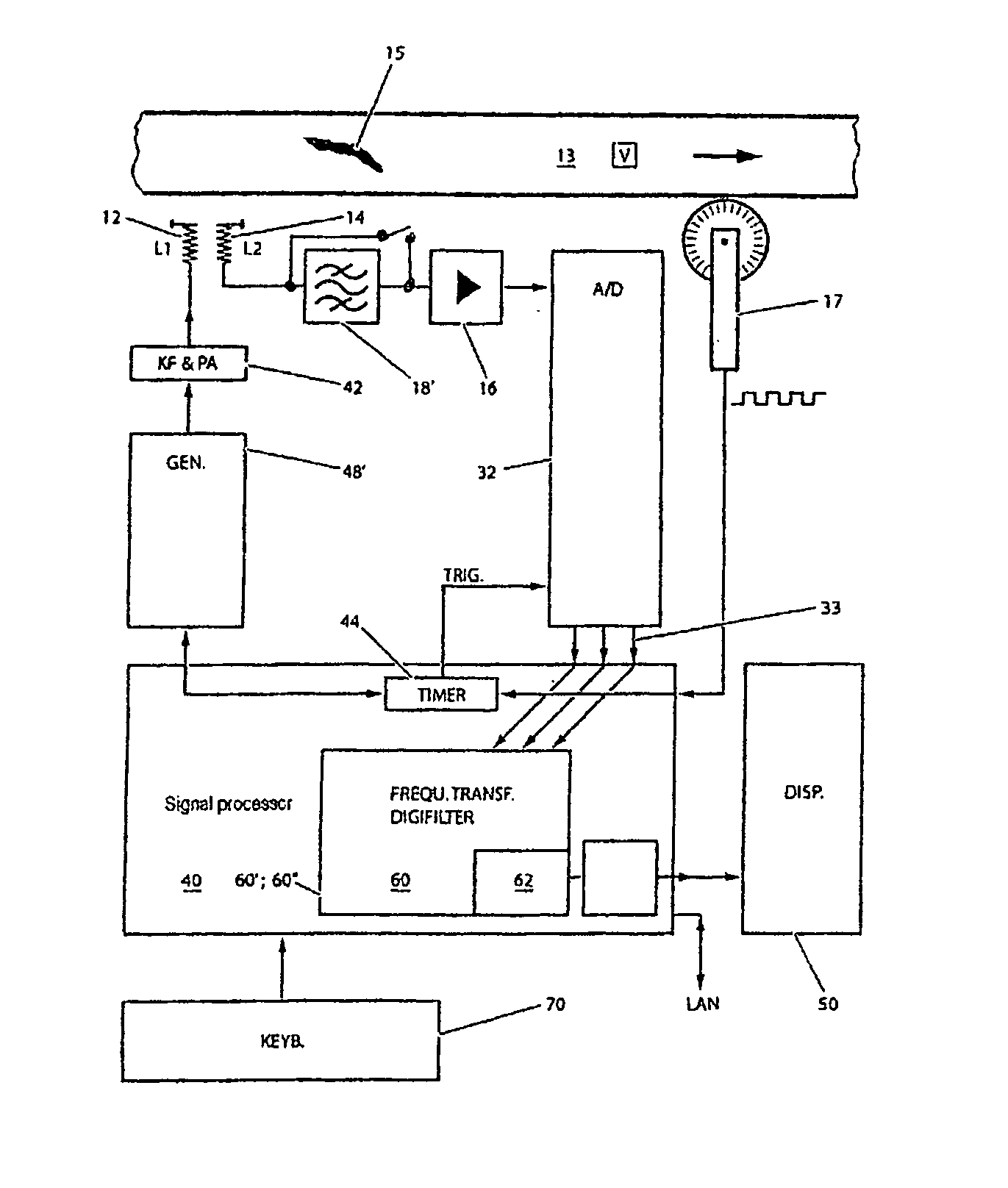
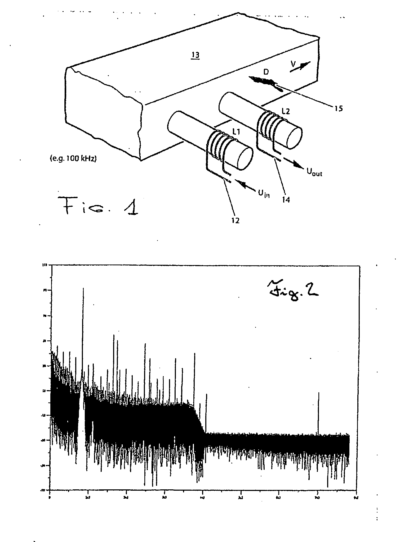
[0047]FIG. 1 schematically shows part of a test specimen 13, represented in the form of an industrial semi-finished product (slab), together with a defect 15 that is present there and is to be detected. The test specimen 13 can move—in a manner known per se—at constant or varying speed parameter “v”) past a test station containing at least one transmitting coil 12 (L1) and at least one receiving coil 14 (L2). The at least one transmitting coil 12 is energized suitably in accordance with the concept of the invention, by means of an essentially constant AC voltage (approximately 1-1200 kHz; if appropriate, also special frequencies). An eddy current signal is tapped off as a received signal at the at least one receiving coil 14. This signal is of the same frequency as the transmitting AC voltage, but may have temporal amplitude fluctuations and / or phase fluctuations caused by on or more defects 15 (cf, FIG. 13 with a single region of reduced amplitude and, if appropriate, altered phase...


PUM


Abstract

Apparatus and associated method for identifying defects on objects provide for—under computer driving—the AC voltage energization of at least one transmitting coil to be simultaneously effected by a carrier signal, and for an essentially amplitude-modulated received signal to be received by means of at least one receiving coil; what is carried out, furthermore, is a demodulation not only of the carrier signal contained in the received signal by means of magnitude and phase formation, but also a demodulation of the harmonics of the carrier which are contained in the received signal, likewise by means of respectively associated magnitude and phase formation, to be precise preferably by using a Fourier or wavelet transformation method.

Description

BACKGROUND OF THE INVENTION [0001] 1. Field of the Invention [0002] The present invention relates to an apparatus and a method which are suitable for locating metallic objects e.g., in the ground, and can also be used for identifying defects on objects. In particular, the invention can be used for identifying defects or faults on metallic objects, and here in particular, on ferromagnetic semifinished or finished products. [0003] 2. Description of Related Art [0004] Similar apparatus and methods of this type have been known for a relatively long time; however, the problem still exists of providing higher-quality portable measuring instruments of the generic type, in particular, those based on an eddy cu-rent measurement technique, or based on an ultrasonic measurement technique or related measurement techniques. SUMMARY OF THE INVENTION [0005] Thus, a primary object of the present invention is to provide a device of the generic type for which the outlay required for its production is...

Claims


Application Information

Patent Timeline
Patent Type & Authority Applications(United States)
IPC IPC(8): H04L27/00
CPCG01N27/90G01N29/043G01N29/11G01N29/46G01N29/27G01N29/42G01N29/449G01N29/2412
Inventor HOELZL, ROLANDHERMANN, MICHAEL
Owner PRUTECHNIK DIETER BUSCH AG
Why Eureka
Try Eureka