Methods and apparatus for obtaining low-dose imaging

a low-dose, imaging technology, applied in the field of radiation imaging, can solve the problems of requiring the object to be exposed to relatively large doses of x-ray radiation and/or over applications with particular safety and/or time constraints, obscuring the true nature of the structure, and difficult to identify or detect tissue anomalies

Inactive Publication Date: 2007-10-18
DEXELA
View PDF7 Cites 81 Cited by
  • Summary
  • Abstract
  • Description
  • Claims
  • Application Information

AI Technical Summary

Problems solved by technology

However, CT imaging often involves obtaining hundreds or thousands of projections to form a 3D reconstruction of the projection data, thus requiring the object to be exposed to relatively large doses of x-ray radiation and / or over applications having particular safety and / or time constraints.
However, the superposition of structure within the breast that occurs when 3D structure is projected onto two dimensions often obscures the true nature of the structure.
This superposition of structure may make it difficult to identify or detect tissue anomalies.
For example, distinct structure in 3D that overlaps in 2D may make it difficult to distinguish cancerous subject matter from benign subject matter within the breast.
In conventional mammography, the inability to ascertain the true nature of breast structure may result in both significant false negative and false positive rates, leading to potential missed early stage cancers in the case of the former, or unnecessary trauma to the patient and / or unnecessary hospital visits, surgical procedures, etc., in the case of the latter.
Similarly, other imaging procedures that solve radiation dose and / or time considerations by acquiring only a limited number of 2D radiographic images are vulnerable to the same risks of misdiagnosis.

Method used


Image

  • Methods and apparatus for obtaining low-dose imaging
  • Methods and apparatus for obtaining low-dose imaging
  • Methods and apparatus for obtaining low-dose imaging

Examples


Embodiment Construction

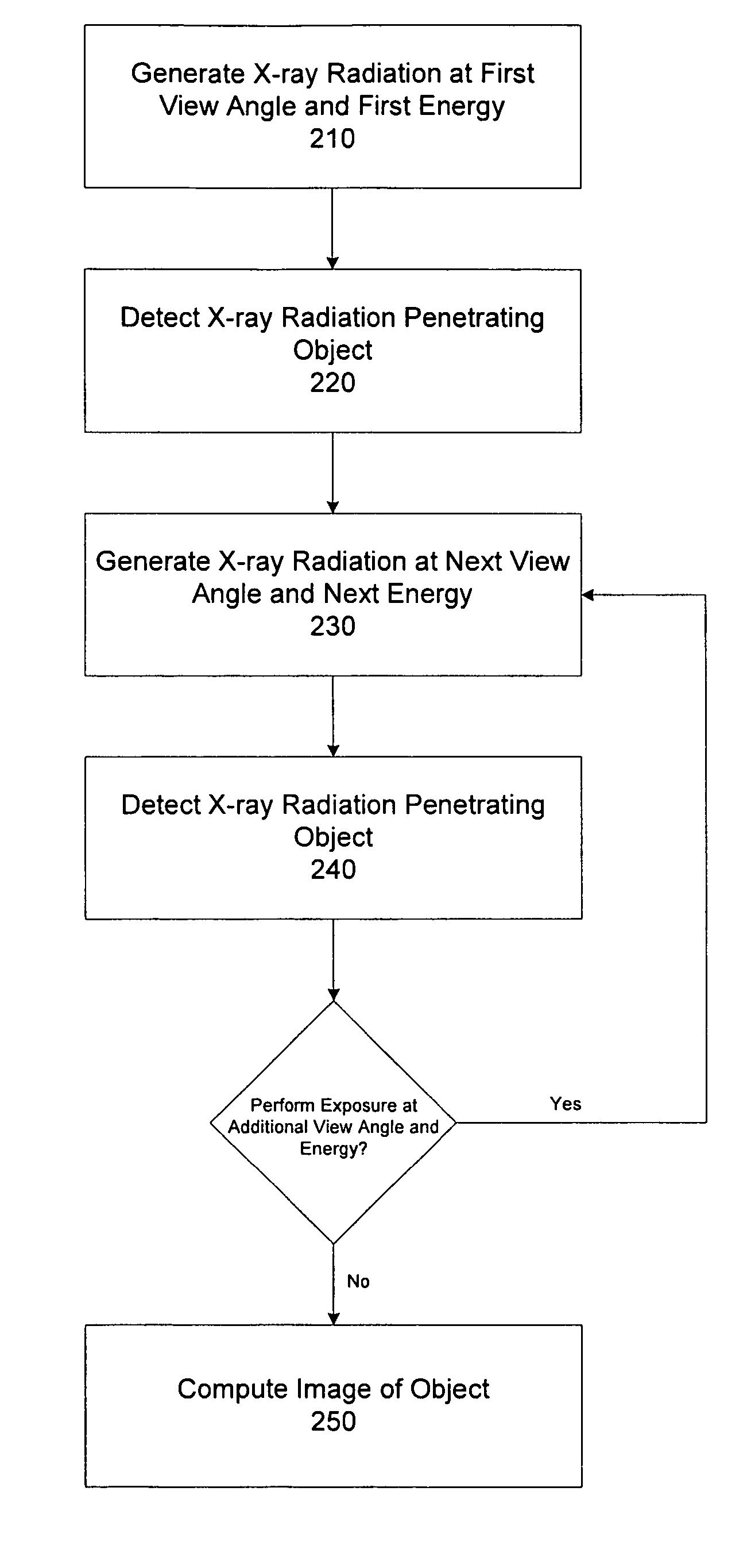
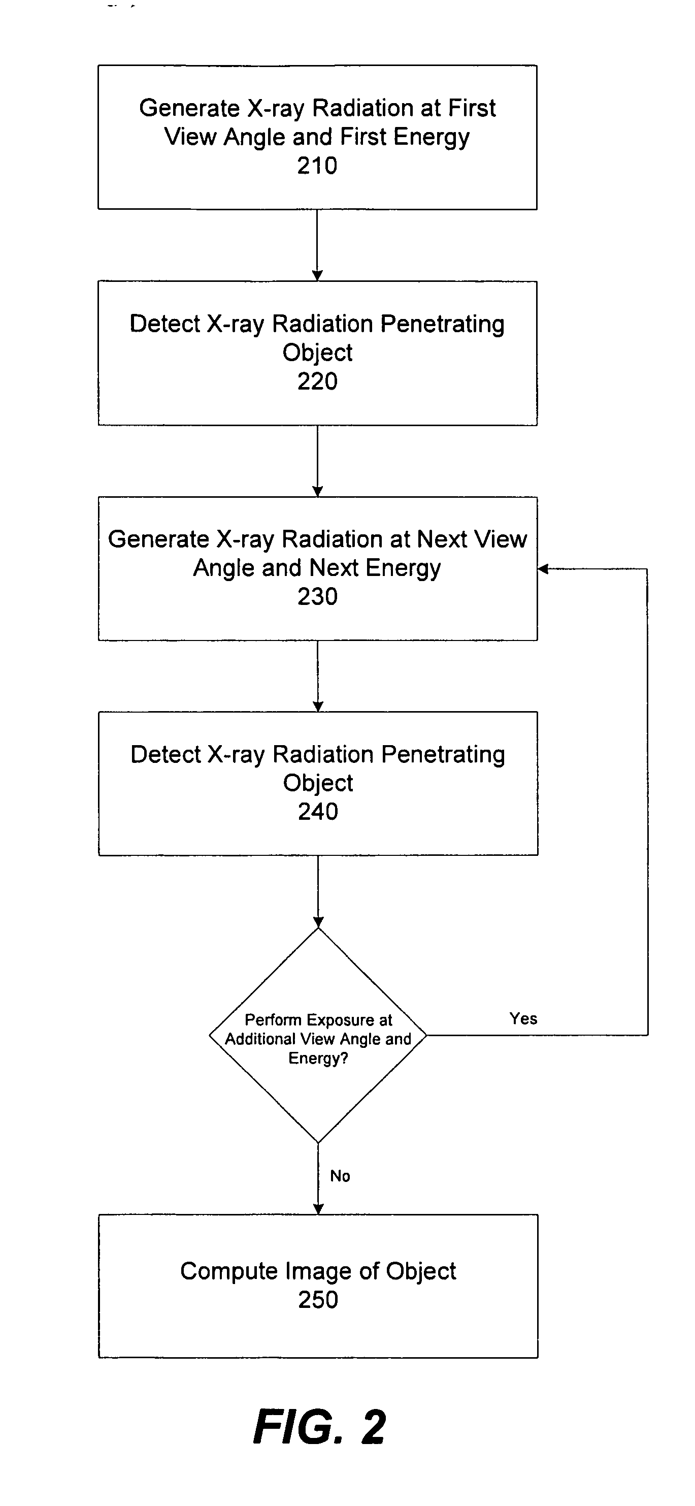
[0015] As discussed above, conventional approaches to providing generally low-dose radiation imaging suffer from images that provide confusing representations of internal structures of an object due, at least in part, to the projection of three-dimensional structure onto one or more two-dimensional images. The resulting superposition of distinct structure located at different levels in 3D makes discerning the actual structure in a 2D representation difficult, rendering conventional imaging procedures vulnerable to errors in diagnosis. Applicant has appreciated that a number of projections obtained using variable radiation doses may be appropriate for acquiring projection data that may be reconstructed to form 3D images, while still respecting a relatively low dose budget (e.g., dose budgets suitable for mammography or other tissue exposures that are generally dose limited due to safety concerns). U.S. Pat. No. 6,744,848 (hereinafter the '848 patent), which is herein incorporated by ...


PUM

PropertyMeasurementUnit
energyaaaaaaaaaa
radiation energyaaaaaaaaaa
view anglesaaaaaaaaaa

Abstract

In one aspect, a method of obtaining projection data of an object from a plurality of view angles with respect to the object is provided. The method comprises acts of providing radiation, at each of the plurality of view angles, to an exposure area in which the object is positioned, controlling a radiation energy of the radiation provided at each of the plurality of view angles such that the respective radiation energy is different for at least two of the plurality of view angles, and detecting at least some of the radiation passing through the exposure area at each of the plurality of view angles to obtain the projection data.

Description

RELATED APPLICATION [0001] This application claims priority under 35 U.S.C. § 119(e) to U.S. Provisional Application Ser. No. 60 / 735140, entitled “Planar Imaging Methods and Techniques,” filed on Nov. 9, 2005, which is herein incorporated by reference in its entirety.FIELD OF THE INVENTION [0002] The present invention relates to radiation imaging, and more particularly, to obtaining projection data of an object by exposing the object to radiation from a plurality of view angles. BACKGROUND OF INVENTION [0003] Imaging apparatus that utilize relatively high energy radiation such as x-ray and gamma rays are widely used to obtain images of subject matter more or less opaque to electromagnetic energy in the visual spectrum. For example, x-ray imaging technology has been employed in a wide range of applications from medical imaging to detection of unauthorized objects or materials in baggage, cargo or other containers. X-ray imaging typically includes passing high energy radiation (i.e., ...

Claims


Application Information

Patent Timeline
Patent Type & Authority Applications(United States)
IPC IPC(8): G01N23/04
CPCA61B6/02A61B6/4035A61B6/4233A61B6/466A61B6/482A61B6/502G01N2223/612G01N23/046G01N2223/423A61B6/4291A61B6/583G01N2223/419A61B6/542A61B6/405A61B6/4085
Inventor STEWART, ALEXANDERSTANTON, MARTINBULLARD, EDWARD
Owner DEXELA
Why Eureka
Try Eureka