Color registration method and image forming apparatus

a color registration and color image technology, applied in electrographic process apparatus, instruments, optics, etc., can solve the problems of crude density of the output image, color misregistration becomes noticeable, image quality deterioration, etc., and achieve the effect of effectively removing a disturbance component and simple configuration

Active Publication Date: 2007-10-18
SHARP KK
View PDF3 Cites 29 Cited by
  • Summary
  • Abstract
  • Description
  • Claims
  • Application Information

AI Technical Summary

Benefits of technology

[0013]The present invention is accomplished in view of the aforesaid circumstances, and firstly provides a technique for effectively removing a disturbance component included in a toner pattern used for a color registration, in order to be capable of precisely adjusting the rotational phase of each photoconductor. Secondly, the present invention provides a technique for suppressing a variation in an image pitch corresponding to the rotational cycle of each photoconductor with a simple configuration, even if a plurality of types of photoconductors, each having a different diameter, are used, whereby a color misregistration is made unnoticeable.

Problems solved by technology

When the color misregistration is great, it might be evaluated that the image quality is deteriorated.
When the phase (rotational phase) of the eccentricity of each photoconductor is not matched, the color misregistration becomes noticeable.
However, the cause of the crude density of the output image, in other words, the cause of the deviation of the formed toner pattern from the expected position, exists in the factors other than the eccentricity of the photoconductor.
A sufficient precision cannot always be obtained in the detection of the rotational phase of each photoconductor using the toner pattern due to the disturbances.
Since the rotational cycle of the black photoconductor is different from those of the other photoconductors, the technique for aligning the direction of the eccentricity to make the color misregistration unnoticeable cannot be taken.

Method used


Image

  • Color registration method and image forming apparatus
  • Color registration method and image forming apparatus
  • Color registration method and image forming apparatus

Examples


Embodiment Construction

[0045]In the present invention described above, the state in which the phases of the speed variation of each photoconductor match to each other means, for example, the state in which the times when the maximum point and minimum point of the variation in the peripheral speed of each photoconductor at the exposure position respectively match to each other. FIG. 16 described later shows an example in which each of YMC photoconductor drums is in this state.

[0046]In other words, the present invention performs the following with respect to the first subject.

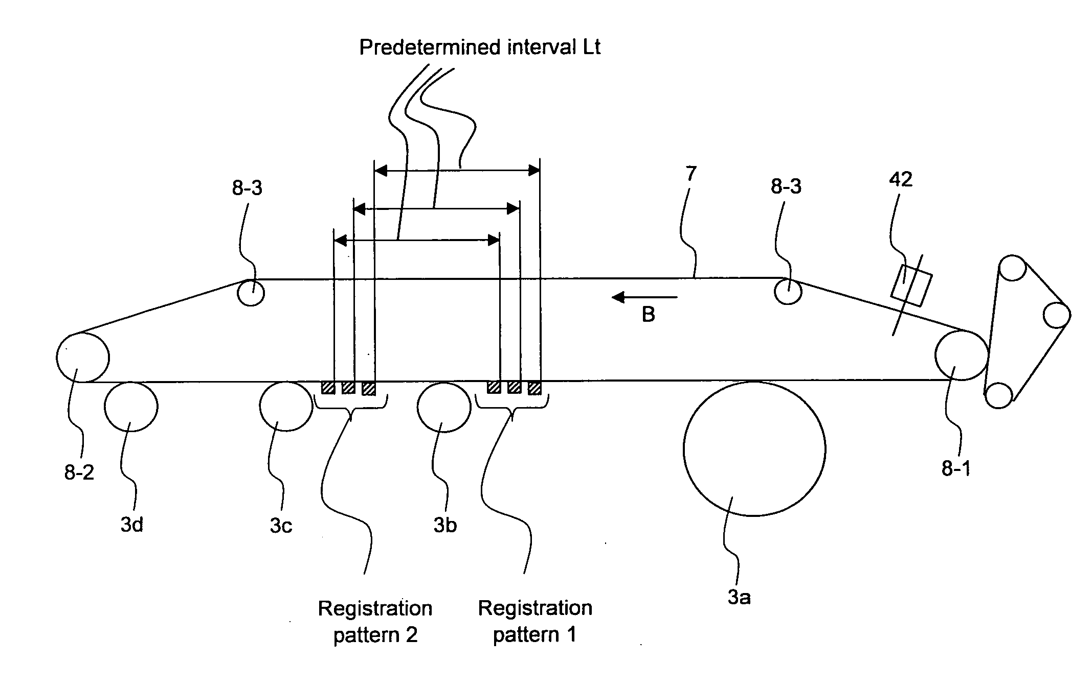
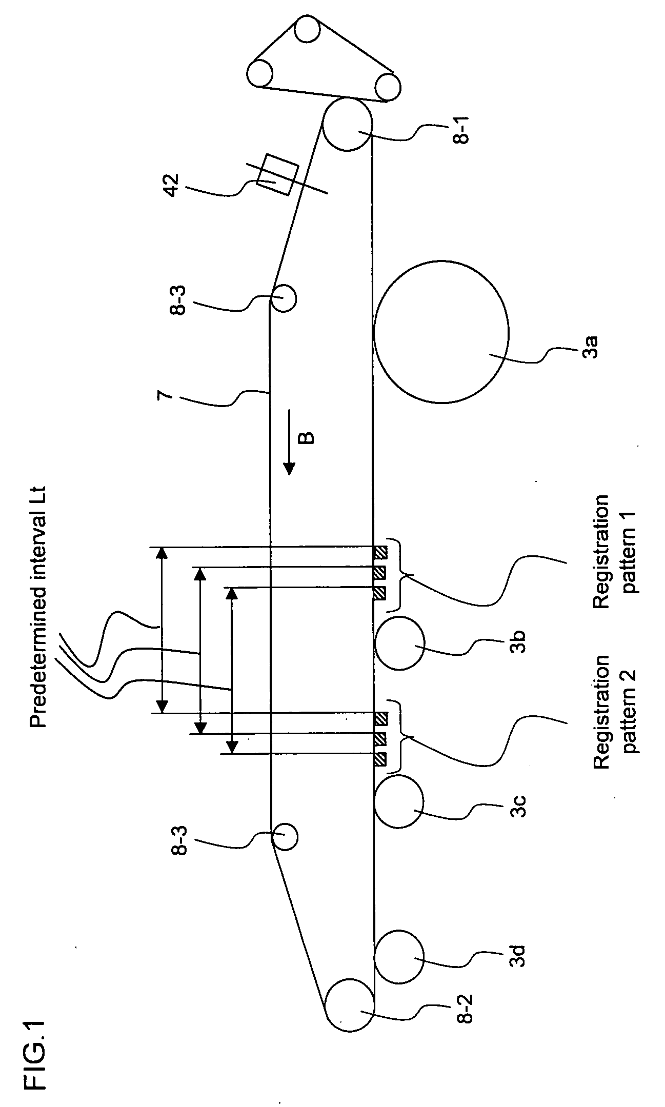
[0047](1) A first toner pattern is formed on a transfer belt, and the position of the formed toner pattern is measured to calculate a misregistration amount (deviation) 1 from the expected position.

[0048](2) Then, a second toner pattern is formed at the position from the first toner pattern at a predetermined interval in the transporting direction of the transfer belt. The position of the formed second toner pattern is measured to calc...


PUM


Abstract

A color registration method in a color image forming apparatus including a plurality of drum-type photoconductors for driving some or all of the photoconductors having the same diameter to match pitch fluctuations which correspond to a rotational cycle of the photoconductors, the method including: a first measurement step for forming a first registration image for each color and measuring formation positions of a plurality of predetermined portions in each registration image; a second measurement step for forming a second registration image for each color and measuring formation positions of a plurality of predetermined portions in each registration image; a calculation step for calculating a periodic fluctuation component being contained in the images in different colors and corresponding to the rotational cycle of the photoconductors so as to obtain phases thereof; and a step for adjusting a rotational phase of the photoconductors in order for the obtained phases matching to each other, wherein the interval between first and second registration images in the rotating direction is set such that disturbance components in which a cycle is assumed beforehand, cancel with each other by calculating the deviation.

Description

CROSS-REFERENCE TO RELATED APPLICATION[0001]This application is related to Japanese patent application Nos. 2006-112604 and 2006-199733 which are filed on Apr. 14, 2006 and Jul. 21, 2006 respectively whose priorities are claimed under 35 USC §119, the disclosure of which are incorporated by reference in its entirety.BACKGROUND OF THE INVENTION[0002]1. Field of the Invention[0003]The present invention relates to a color registration method and a color image forming apparatus.[0004]2. Description of the Related Art[0005]There has been known a color image forming apparatus (so-called tandem-type color image forming apparatus) having a plurality of drum-type photoconductors. In the color image forming apparatus, it is important to suppress the positional deviation for every color (color misregistration) to an unnoticeable degree. When the color misregistration is great, it might be evaluated that the image quality is deteriorated. The greatest factor of the color misregistration is a pe...

Claims


Application Information

Patent Timeline
Patent Type & Authority Applications(United States)
IPC IPC(8): G03G15/01
CPCG03G15/0194G03G2215/0161
Inventor MATSUYAMA, KENGOHARADA, YOSHIKAZUTOMITA, NORIOKIKUCHI, YOSHITERUFUJITA, HIROKAZU
Owner SHARP KK
Why Eureka
Try Eureka