
Liquid container

a liquid container and liquid technology, applied in the field of liquid containers, can solve the problems of inability to detect the change in the vibration wave form, the liquid ejection head is likely to be damaged, etc., and achieve the effect of accurately detecting the liquid exhausted and minimizing the volume of the liquid detection chamber

Inactive Publication Date: 2007-10-18
SEIKO EPSON CORP
View PDF6 Cites 26 Cited by
  • Summary
  • Abstract
  • Description
  • Claims
  • Application Information

AI Technical Summary

Benefits of technology

[0009] An advantage of some aspects of the invention is to provide a liquid container that has a liquid detection portion for stably detecting a liquid with high accuracy while preventing bending or wrinkle of a flexible pouch containing a liquid from affecting detection accuracy of the liquid residual quantity. The advantage can be attained by at least one of the following aspects:
[0015] With this configuration, when a part constituting the pair of opposing walls of the liquid detection chamber is an injection molded product formed of resin, the protrusion can be integrally formed at the surface of the opposing wall, such that the number of parts is not increased. That is, manufacturing costs can be prevented from being increased due to the increase in the number of parts.
[0029] With this configuration, the ink residual quantity in the ink container that supplies ink to the ink jet recording apparatus can be accurately detected. Accordingly, a trouble can be prevented from occurring due to degradation of the detection accuracy or erroneous detection of the ink residual quantity. Therefore, operation reliability in the ink jet recording apparatus can be improved.
[0031] In addition, even if the liquid in the liquid containing chamber is exhausted and the volume of the liquid detection chamber is minimized, a predetermined space is secured between the detection unit and the opposing wall in the liquid detection chamber. Accordingly, if the detection unit is normally operating, the vibration wave form corresponding to the amount of the liquid remaining in the space is detected. Therefore, there is no case where the change in the vibration wave form cannot be detected due to a failure of the detection unit or the like or it is erroneously detected that the liquid is exhausted. As a result, it is possible to accurately detect that the liquid is exhausted.

Problems solved by technology

However, if the liquid ejection head operates in a state where the liquid is not supplied, so-called idle printing occurs, and thus the liquid ejection head is likely to be damaged.
Therefore, there is no case where the change in the vibration wave form cannot be detected due to a failure of the detection unit or the like or it is erroneously detected that the liquid is exhausted.

Method used


Image

  • Liquid container
  • Liquid container
  • Liquid container

Examples


first embodiment

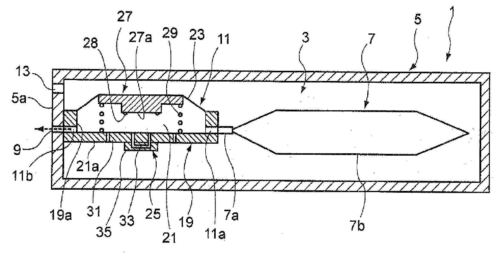
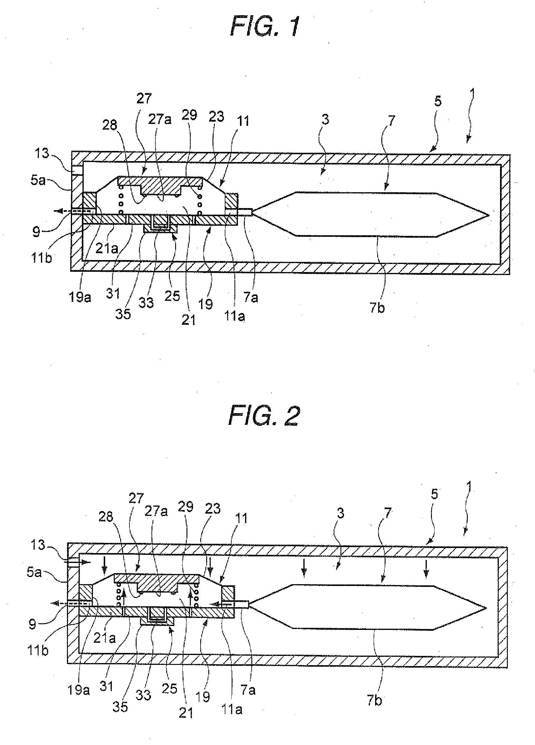
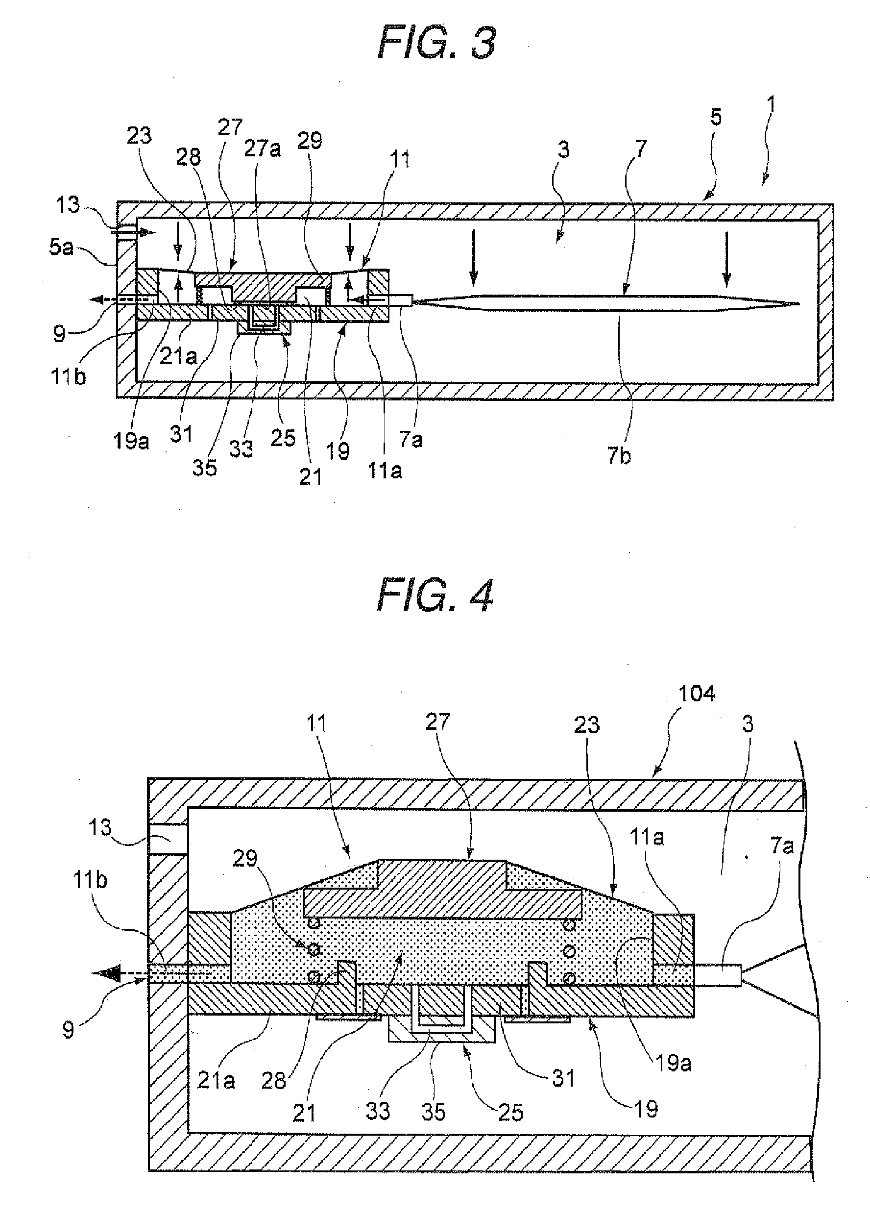
[0047]FIG. 1 is a longitudinal cross-sectional view showing a liquid container according to the invention in a state where a liquid remains in a liquid containing chamber and a pressure space is not pressurized. FIG. 2 is a longitudinal cross-sectional view showing a state where a liquid remains in a liquid containing chamber and a pressure space is pressurized. FIG. 3 is a longitudinal cross-sectional view showing a state where a liquid in a liquid containing chamber is exhausted and a pressure space is pressurized.

[0048] A liquid container 1 is an ink cartridge that is detachably mounted on a cartridge of an ink jet recording apparatus and supplies ink to a recording head (liquid ejection head) provided in the recording apparatus.

[0049] The liquid container 1 includes a container main body 5 that partitions a pressure space (herein after referred to as an airtight space 3) to be pressurized by a pressure unit (not shown), a liquid containing chamber 7 that stores ink, is accommod...

seventh embodiment

[0110] Like a sixth or seventh embodiment described below, the liquid detection portion 11 can be disposed in an external exclusive-use accommodating space separated from the airtight space 3, in which the liquid containing chamber 7 is accommodated.

sixth embodiment

[0111]FIG. 11 is a longitudinal cross-sectional view showing a liquid container according to the invention in a state where a liquid remains in a liquid containing chamber and an airtight space, in which a liquid containing chamber is provided, is not pressurized. FIG. 12 is an enlarged cross-sectional view of a liquid container shown in FIG. 11, which shows a state where a liquid is absorbed from a non-pressurized liquid containing chamber through a liquid supply port.

[0112] In a liquid container 102 of the sixth embodiment, the liquid detection portion 11 in the liquid container 1 of the first embodiment is moved to a separately partitioned detection unit accommodating chamber 15 outside the airtight space 3, in which the liquid containing chamber 7 is accommodated.

[0113] Further, as the liquid detection portion 11 is changed to a detection unit accommodating chamber 15 outside the airtight space 3, the arrangement of the pressure adjusting spring 29 that urges the diaphragm 23 o...


PUM


Abstract

A liquid container includes: a liquid containing chamber that is accommodated in a pressure space and is pressurized by a pressurized fluid to be introduced into the pressure space so as to discharge a liquid stored in an inside thereof; and a liquid detection portion for detecting the liquid in the liquid containing chamber, the liquid detection portion includes: a liquid detection chamber that has a liquid inlet port communicating with the liquid containing chamber and a liquid outlet port communicating with an external liquid consuming apparatus, and a volume of which changes according to a liquid pressure between the liquid inlet port and the liquid outlet port; a detection unit that is provided on one of first and second walls opposite to each other, a distance between the first and second walls changing in accordance with the change in volume of the liquid detection chamber, for detecting a vibration wave form of the liquid; and a space forming portion that, when the volume of the liquid detection chamber is minimized, forms a predetermined space between the first and second walls.

Description

BACKGROUND [0001] 1. Technical Field [0002] The present invention relates to a liquid container that supplies a predetermined liquid to a liquid consuming apparatus, for example, a liquid ejection head ejecting a liquid droplet. [0003] 2. Related Art [0004] A liquid ejection head of a textile printing apparatus, a micro dispenser, or a commercial recording apparatus that requires ultra high printing quality receives a liquid ejected from a liquid container. However, if the liquid ejection head operates in a state where the liquid is not supplied, so-called idle printing occurs, and thus the liquid ejection head is likely to be damaged. In order to prevent this problem, it is necessary to monitor a liquid residual quantity in the container. [0005] As the recording apparatus, there are suggested various apparatuses that have a liquid detection portion for detecting an ink in an ink cartridge as a liquid container. [0006] The specific structure of such a liquid detection portion is des...

Claims


Application Information

Patent Timeline
IPC IPC(8): G01N21/00
CPCB41J2002/17583B41J2/17566
Inventor AOKI, YUJIKIMURA, HITOTOSHI
Owner SEIKO EPSON CORP
Learn More