Transmission apparatus

a technology of transmission apparatus and gear sounding, which is applied in the direction of gearing control, gearing elements, gearing, etc., can solve the problems of increasing the need for fuel mileage improvement, increasing the cost of fuel, and generating gear sounding in which sound or noise is generated

Inactive Publication Date: 2007-10-18
MITSUBISHI ELECTRIC CORP
View PDF9 Cites 7 Cited by
  • Summary
  • Abstract
  • Description
  • Claims
  • Application Information

AI Technical Summary

Benefits of technology

[0019]Accordingly, the present invention is intended to obviate the problems as referred to above, and has for its object to provide a transmission apparatus that can perform a shift operation in a quick manner without generating tooth contact and gear noise when shifting a transmission gear to a nonsynchronized gear train.

Problems solved by technology

In addition, in recent years, regulations or restrictions on fuel mileage or economy is becoming severe, and hence improvements in fuel mileage is increasingly required.
Therefore, in case where the gear is shifted to the nonsynchronized gear train, a gear change or shift might not be made due, for example, to the occurrence of tooth contact of the gear wheels in which the crests of the gear wheels are placed in contact with each other when the rotation speed of the input shaft is too low, whereas when the rotation speed of the input shaft is too high, the gear wheels might become unable to come into engagement with each other in a smooth manner, generating gear sounding in which sound or noise is generated.
In the conventional automatic transmission apparatus for a vehicle, however, there is the following problem.
That is, it is impossible to perform the reduction of the rotation speed of the countershaft due to a shift to the synchronized stage and a shift operation to the nonsynchronized stage in parallel with respect to each other in view of the construction thereof, so a long time is required for a shift operation from the start to the end or completion of the gear shift.
In addition, there is also another problem that it is necessary to return the transmission to the neutral stage when a shift is made from the synchronized stage to the nonsynchronized stage, so the rotation speed of the countershaft might become irregular, thus generating tooth contact or gear sounding

Method used


Image

  • Transmission apparatus
  • Transmission apparatus
  • Transmission apparatus

Examples


embodiment 1

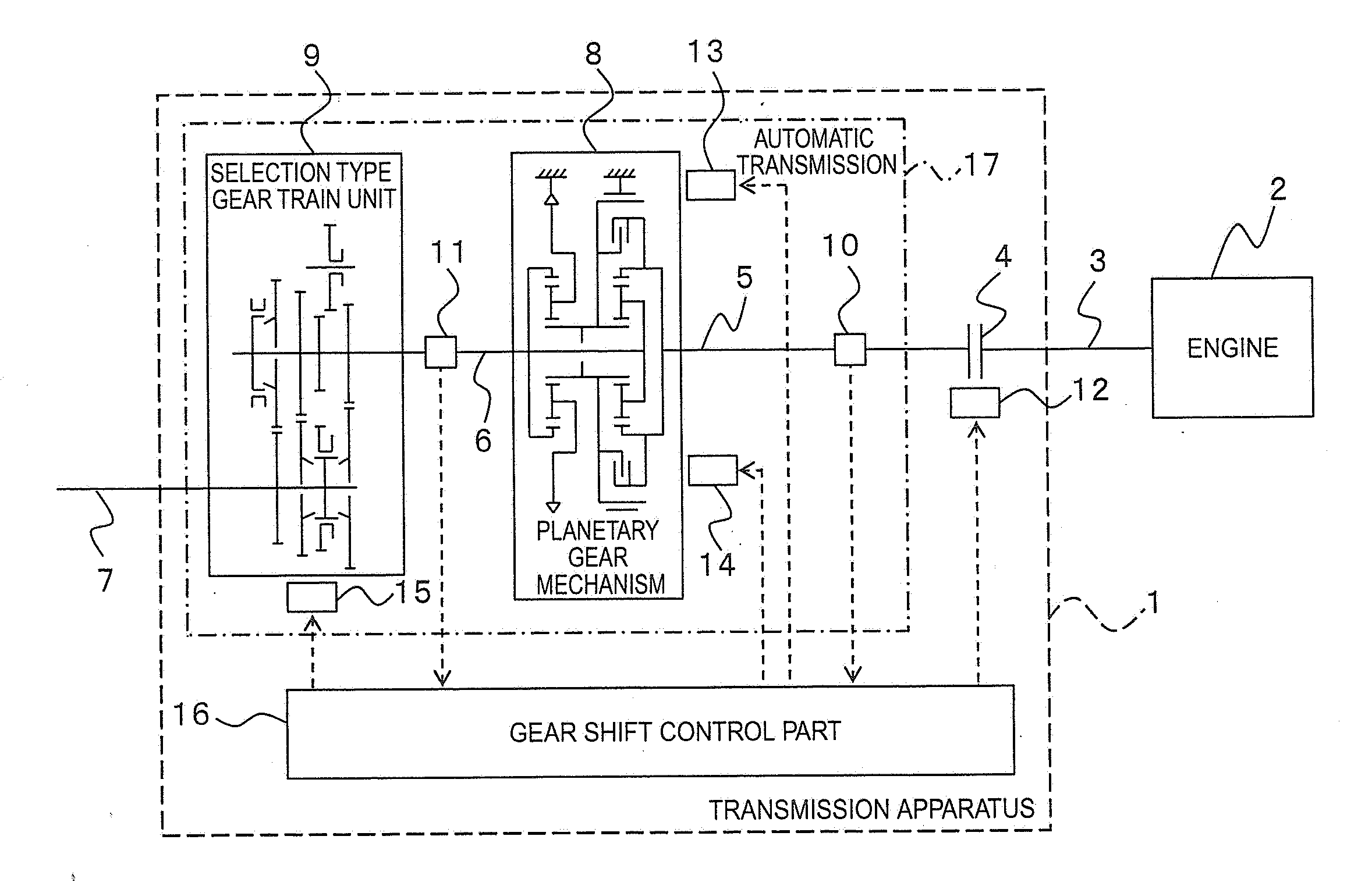
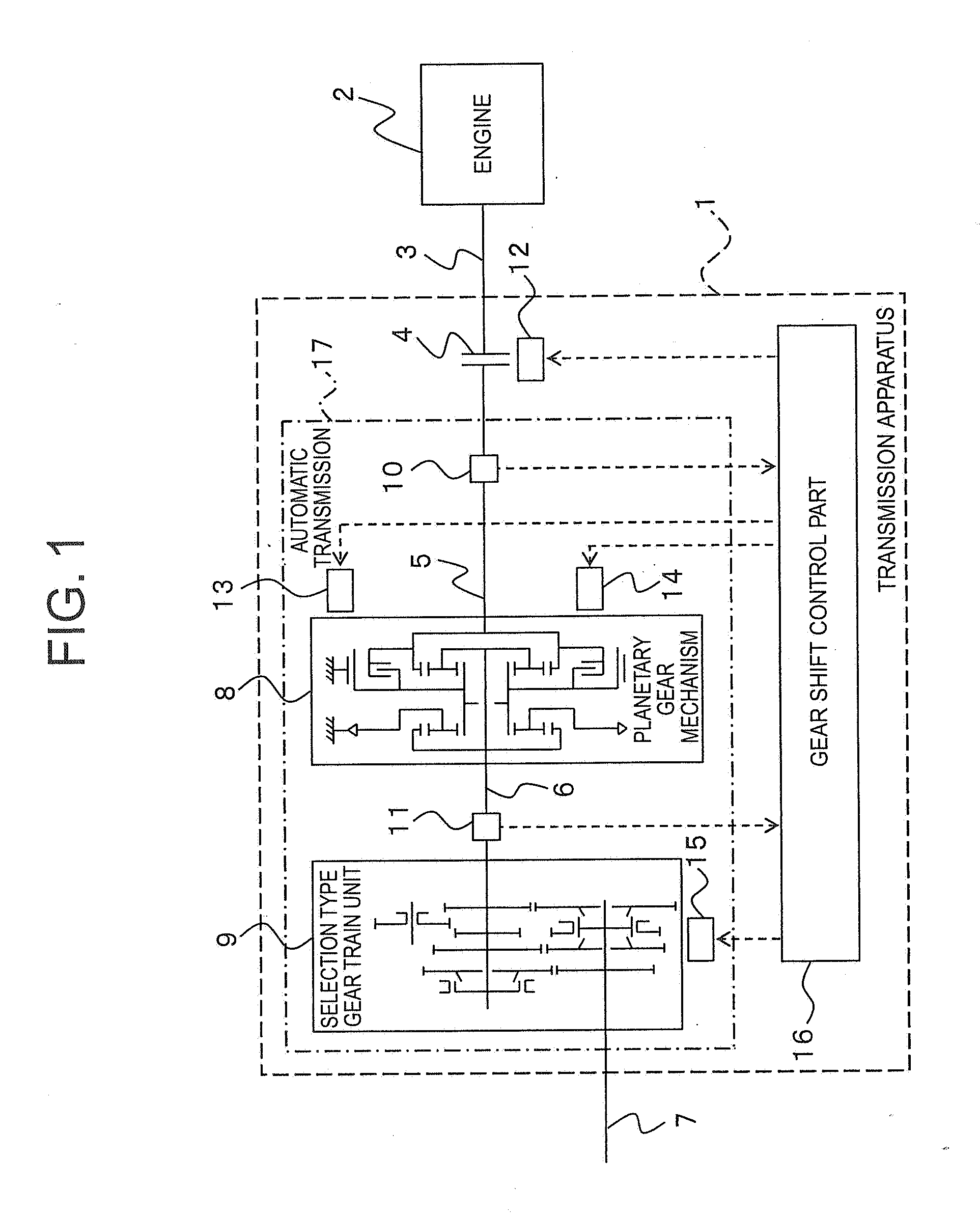
[0034]Referring to the drawings and first to FIG. 1, there is shown a transmission apparatus 1 according to a first embodiment of the present invention, together with an engine 2.

[0035]In FIG. 1, the transmission apparatus 1 includes a crankshaft 3, a first clutch 4, a first input shaft 5, a second input shaft 6, an output shaft 7, a planetary gear mechanism 8, a selection type gear train unit 9, a first rotation speed sensor (first rotation speed detection part) 10, a second rotation speed sensor (second rotation speed detection part) 11, a first clutch actuator 12, a band brake actuator 13, a direct clutch actuator (second clutch actuator) 14, a shift actuator 15, and a gear shift control part 16.

[0036]Here, note that the first input shaft 5, the second input shaft 6, the output shaft 7, the planetary gear mechanism 8, the selection type gear train unit 9, the first rotation speed sensor 10, the second rotation speed sensor 11, the band brake actuator 13, the direct clutch actuato...

embodiment 2

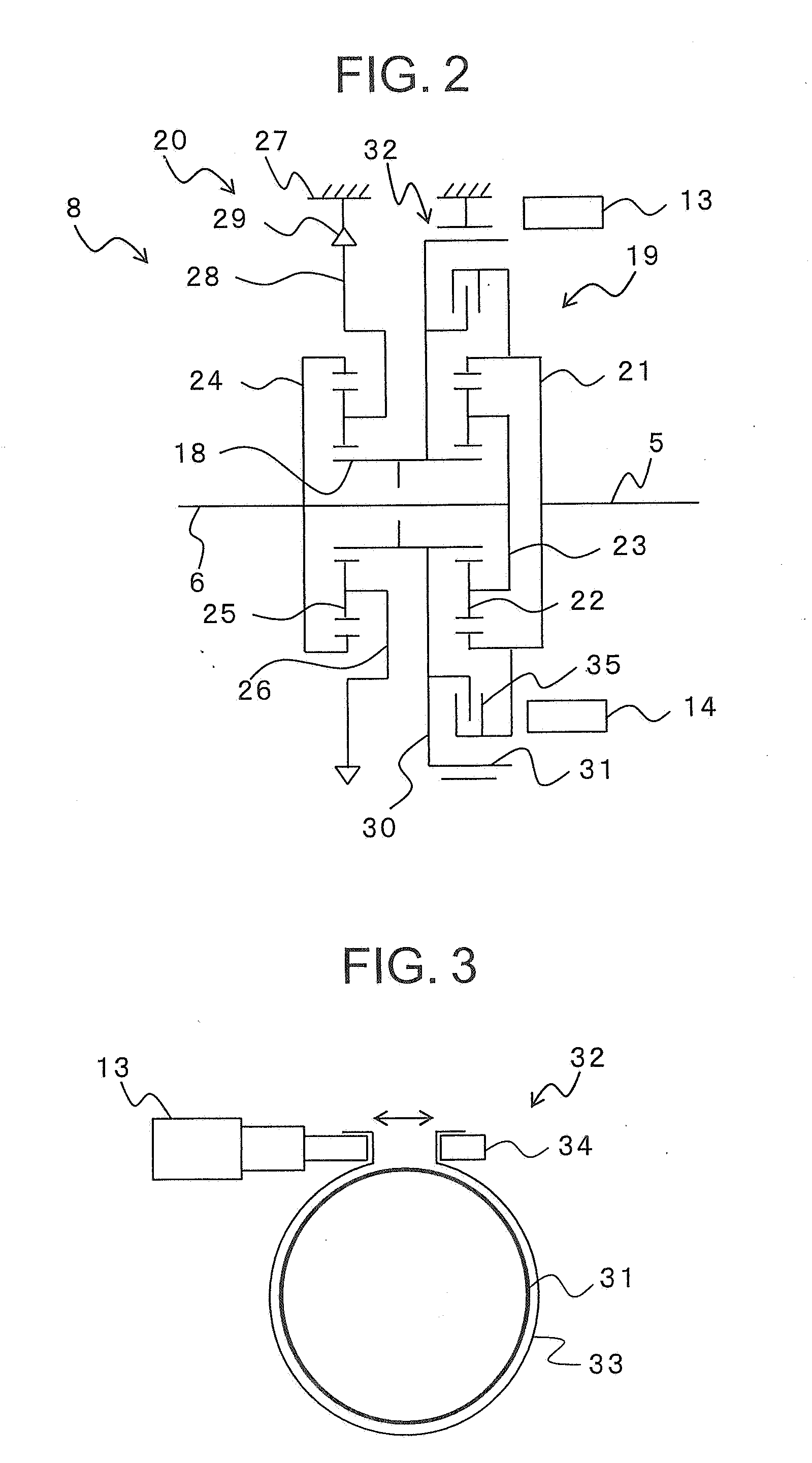
[0097]In the above-mentioned first embodiment, upon generation of a shift request, the gear shift control part 16 releases the first clutch 4, tightens the band brake 32, and connects the direct clutch 35 thereby to reduce the rotation speed of the second input shaft 6, but the present invention is not limited to this.

[0098]Thus, the gear shift control part 16 may reduce the rotation speed of the second input shaft 6 by changing the transmission gear ratio of the planetary gear mechanism 8 with the clutch being connected.

[0099]Hereinbelow, reference will be made to the processing of reducing the rotation speed of the second input shaft 6 by switching or changing the transmission gear ratio of the planetary gear mechanism 8.

[0100]The configuration or construction of a transmission apparatus according to a second embodiment of the present invention is the same as that of the above-mentioned first embodiment, and hence a detailed explanation thereof is omitted.

[0101]Here, note that whe...


PUM


Abstract

A transmission apparatus can perform a shift operation quickly without generating tooth contact and gear noise when shifting to a nonsynchronized gear train. The apparatus includes a first clutch; a first and a second input shaft; an output shaft; a planetary gear mechanism having a first and a second planetary gear train, a band brake and a direct clutch; a selection type gear train unit having a nonsynchronized gear train; a second rotation speed detector for detecting the rotation speed of the second input shaft as a second rotation speed; actuators; and a gear shift control part for controlling the actuators. When a request for shift to the nonsynchronized gear train is generated, the first clutch is released, the band brake is tightened, and the direct clutch is connected to reduce the second rotation speed. When the second rotation speed becomes equal to or less than a predetermined speed, a gear shift is executed.

Description

BACKGROUND OF THE INVENTION[0001]1. Field of the Invention[0002]The present invention relates to a transmission apparatus installed on a vehicle such as for example a motor vehicle.[0003]2. Description of the Related Art[0004]In general, a motor vehicle is provided with a transmission for converting the power of an engine into a torque and a rotation speed corresponding to the operating state of the engine. As such a transmission, there have been proposed a manual transmission that changes the transmission gear ratio by shifting gear trains by a manual operation, an automatic transmission that changes the transmission gear ratio by automatically shifting gear trains in accordance with the operating condition of an engine by using a driving unit, and so on.[0005]In addition, in recent years, regulations or restrictions on fuel mileage or economy is becoming severe, and hence improvements in fuel mileage is increasingly required.[0006]Accordingly, there has been proposed an automatic ...

Claims


Application Information

Patent Timeline
Patent Type & Authority Applications(United States)
IPC IPC(8): F16H37/02
CPCF16H61/0403F16H2306/48F16H61/702
Inventor OGATA, TOMOAKI
Owner MITSUBISHI ELECTRIC CORP
Why Eureka
Try Eureka