Diagnostic Ultrasound System and Method of Displaying Elasticity Image

a technology of ultrasound system and elasticity image, applied in the field of diagnostic ultrasound system, can solve the problems of non-uniform stress distribution in living tissue, deviating from a predetermined compression direction, and unable to uniformly apply pressure to the object to be examined, so as to achieve accurate and easy grasping of the compression state

Active Publication Date: 2007-10-18
FUJIFILM HEALTHCARE CORP
View PDF11 Cites 41 Cited by
  • Summary
  • Abstract
  • Description
  • Claims
  • Application Information

AI Technical Summary

Benefits of technology

[0011] In other words, the compression data corresponds to stress generated in the body tissue. Therefore, the determination result based on the compression data can be used as an objective determination index for grasping the compression state (for example, the adequate compression range or the compression direction) of the body tissue. By reflecting the determination result on an elasticity image, the elasticity image can be used to objectively and quantitatively identify the adequate compression range or the compression direction. By visually confirming such an elasticity image, examiners can accurately and easily grasp the compression state (for example, the adequate compression range or the compression direction) on a displayed image, regardless of their experience.
[0012] In such a case, the compression state evaluating means can determine an adequate compression range of the body tissue on the basis of a result of comparing the magnitude of the compression data and a set value.

Problems solved by technology

Therefore, when compressing the object to be examined, the compression direction may deviate from a predetermined direction due to tilting of the ultrasound transmission and reception surface.
As a result, pressure may not be uniformly applied to the object to be examined.
In other words, a non-uniform stress distribution may be generated in the living tissue of the object to be examined.
When an elasticity image related to such living tissue is displayed, it is difficult to determined, for example, whether an image corresponding to an inadequate compression range is caused by non-uniformity of the stress distribution or caused by the hardness of the living tissue.
However, the process of identifying an adequate compression range and an inadequate compression range in a displayed image depends on the examiner's experience.

Method used


Image

  • Diagnostic Ultrasound System and Method of Displaying Elasticity Image
  • Diagnostic Ultrasound System and Method of Displaying Elasticity Image
  • Diagnostic Ultrasound System and Method of Displaying Elasticity Image

Examples


Embodiment Construction

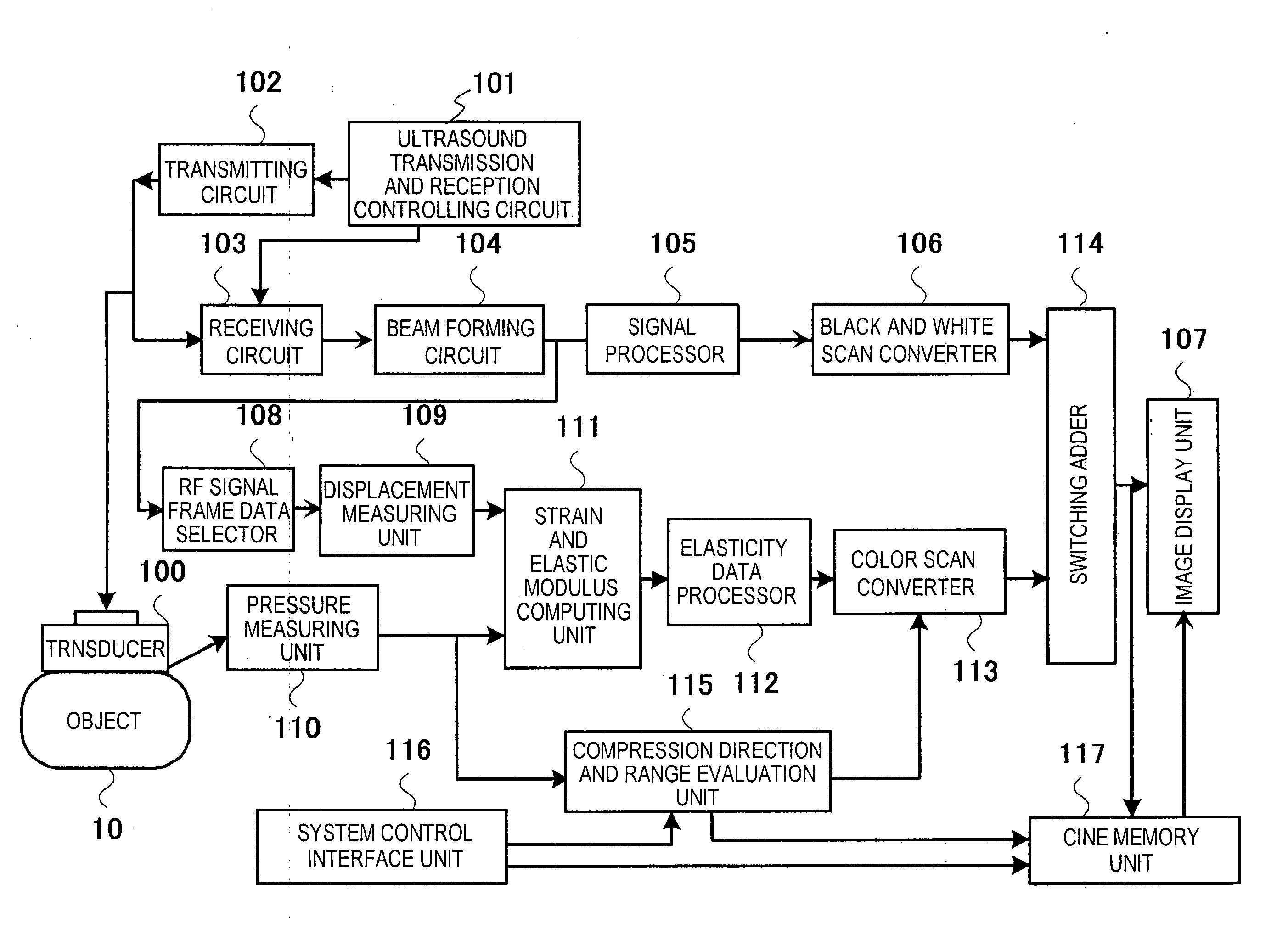
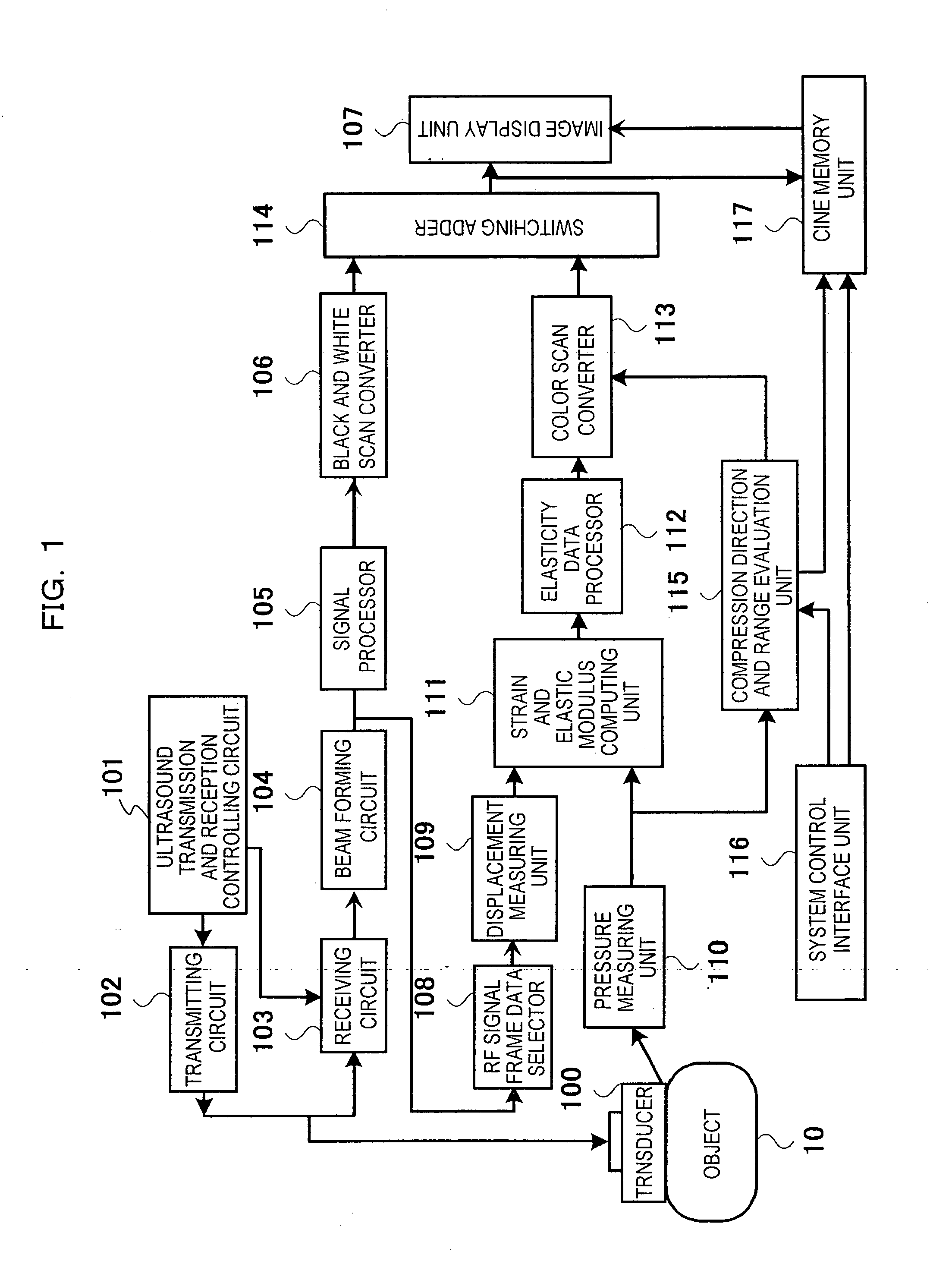
[0062] A first embodiment of a diagnostic ultrasound system and a method of displaying an elasticity image employing the present invention will be described with reference to the drawings. FIG. 1 is a block diagram illustrating the configuration of the diagnostic ultrasound system according to this embodiment. The diagnostic ultrasound system captures a cross-sectional image of a region to be diagnosed of a object to be examined 10 by transmitting and receiving ultrasonic waves to and from the object to be examined 10 and captures an elasticity image representing the hardness or softness of living tissue of the region to be diagnosed.

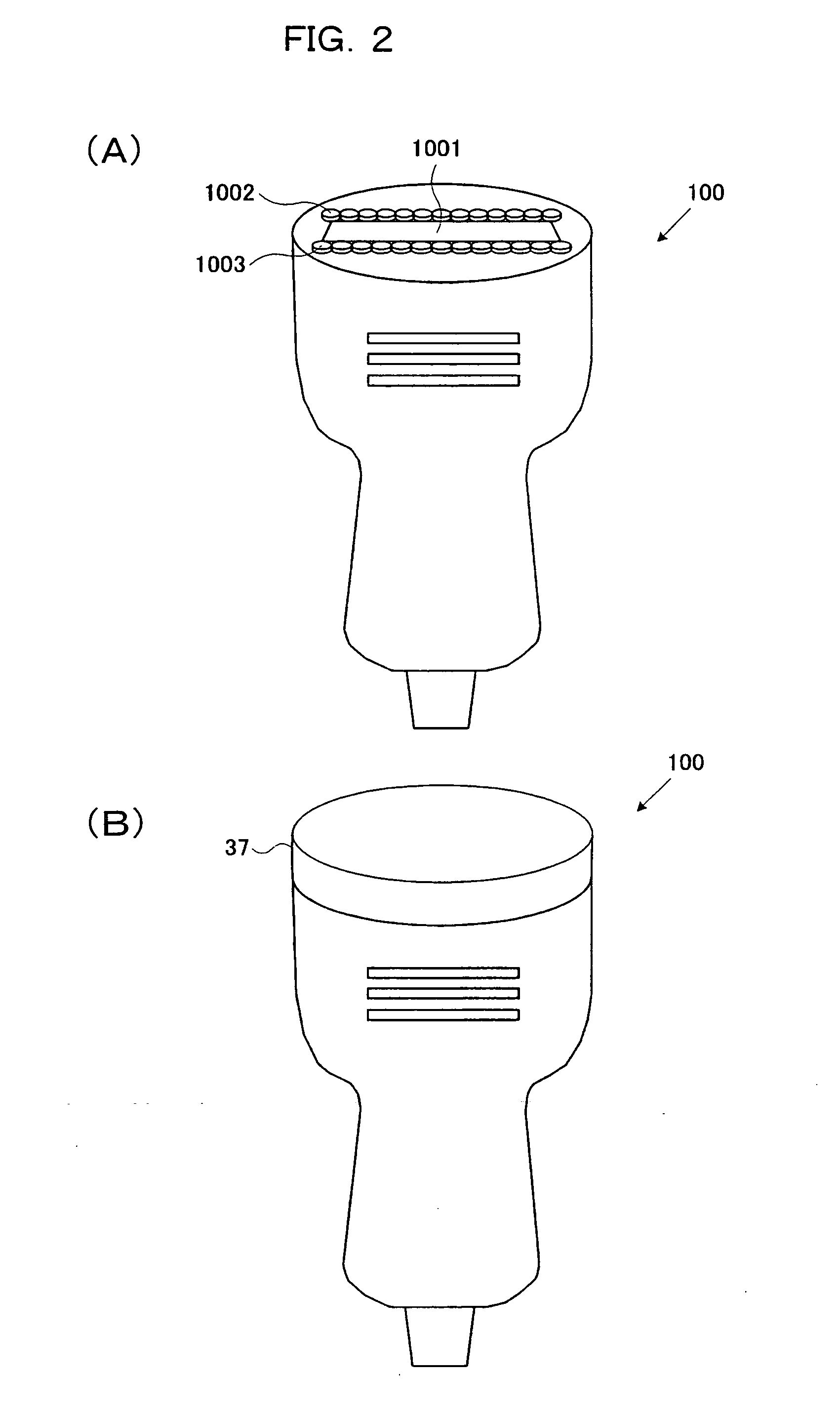
[0063] As shown in FIG. 1, the diagnostic ultrasound system includes an ultrasound transducer 100 (hereinafter referred to as ‘probe 100’) for transmitting and receiving ultrasonic waves to and from the object to be examined 10, a transmitting circuit 102 that is a transmitting means for supplying a driving signal for transmission to the probe 100, a r...


PUM


Abstract

A diagnostic ultrasound system includes an ultrasound transmitting and receiving system for transmitting and receiving ultrasonic waves to and from a object to be examined 10, an elasticity image capturing system for capturing an elasticity image related to body tissue of the object to be examined on the basis of a signal output from the ultrasound transmitting and receiving system, and a controlling and displaying system for capturing the elasticity image. The elasticity image capturing system obtains compression data related to the compression state of the object to be examined 10, determines the compression state of the body tissue on the basis of the compression data, and includes a compression direction and range evaluation unit 115 as a compression state evaluating means for reflecting the determination result to the elasticity image. In this way, more accurate diagnosis by objectively and quantitatively grasping the compression state of the body tissue is possible.

Description

TECHNICAL FIELD [0001] The present invention relates to a diagnostic ultrasound system for displaying an elasticity image representing the hardness or softness of living tissue of a object to be examined. BACKGROUND ART [0002] A diagnostic ultrasound system for capturing an ultrasound image of a object to be examined supplies a driving signal for transmission to an ultrasound transducer, emits an ultrasonic wave to the object to be examined, and reconstructs and displays an ultrasound image on the basis of the signal received at the ultrasound transducer. [0003] As such a diagnostic ultrasound system, there is one that displays an elasticity image representing the hardness or softness of living tissue of a object to be examined. For example, an examiner manually compresses an ultrasound transducer whose ultrasound transmission and reception surface is in contact with the object to be examined against the object to be examined. The diagnostic ultrasound system obtains time-sequential...

Claims


Application Information

Patent Timeline
Patent Type & Authority Applications(United States)
IPC IPC(8): A61B8/00A61B8/08
CPCA61B8/08A61B8/4254A61B8/485A61B8/463
Inventor MATSUMURA, TAKESHI
Owner FUJIFILM HEALTHCARE CORP
Why Eureka
Try Eureka