Audio signal encoding method, program of audio signal encoding method, recording medium having program of audio signal encoding method recorded thereon, and audio signal encoding device

a technology of audio signal and encoding method, which is applied in the direction of code conversion, speech analysis, instruments, etc., can solve the problems of heavy processing load in the encoding process in the past, and achieve the effect of reducing processing load and reducing processing load

Inactive Publication Date: 2007-10-18
SONY CORP
View PDF7 Cites 36 Cited by
  • Summary
  • Abstract
  • Description
  • Claims
  • Application Information

AI Technical Summary

Benefits of technology

[0034] The present invention has been made in view of the above, and it is desirable to provide an audio signal encoding method, a program of the audio signal encoding method, a recording medium having the program of the audio signal encoding method recorded thereon, and an audio signal encoding device that can reduce the load of processing as compared with an existing example when an audio signal is encoded on the basis of psychoacoustic analysis.
[0039] According to the configurations of the above-described embodiments, evaluation criteria for bit allocation may be sorted in advance and a subband signal to which to allocate bits may be detected. When a recalculated evaluation criterion is to be sorted, the evaluation criterion may be sorted by partly changing the sequence of a latest sort result. It is therefore possible to detect a subband signal to which to allocate bits by a simpler process as compared with the existing example. Hence, when an audio signal is encoded on the basis of psychoacoustic analysis, the load of processing may be reduced as compared with the existing example.
[0040] According to the present invention, when an audio signal is encoded on the basis of psychoacoustic analysis, the load of processing may be reduced as compared with the existing example.

Problems solved by technology

Therefore the encoding process in the past has a problem of a heavy processing load.

Method used


Image

  • Audio signal encoding method, program of audio signal encoding method, recording medium having program of audio signal encoding method recorded thereon, and audio signal encoding device
  • Audio signal encoding method, program of audio signal encoding method, recording medium having program of audio signal encoding method recorded thereon, and audio signal encoding device
  • Audio signal encoding method, program of audio signal encoding method, recording medium having program of audio signal encoding method recorded thereon, and audio signal encoding device

Examples


first embodiment

(1) Configuration of Embodiment

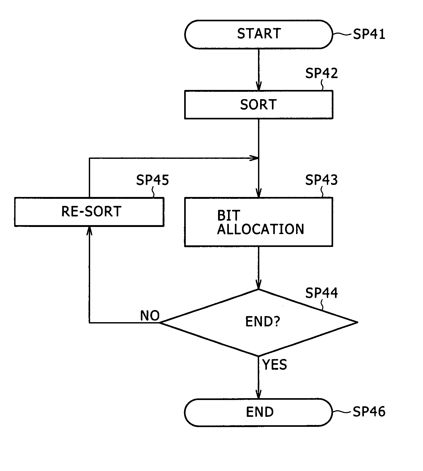
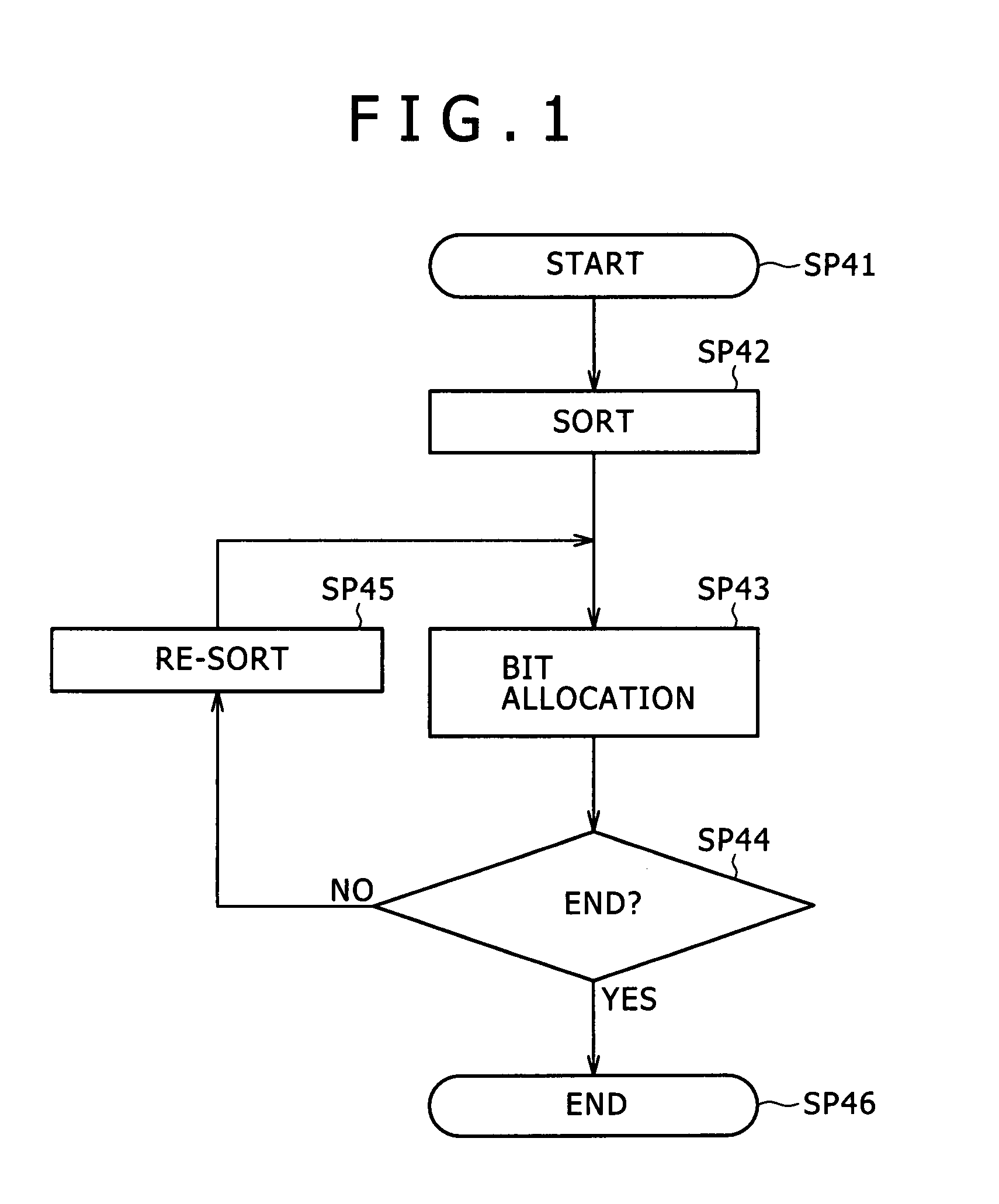
[0061]FIG. 1 is a flowchart of a processing procedure of a dynamic bit allocation unit 4 in an encoder according to a first embodiment of the present invention, for comparison with FIG. 17. The encoder according to the first embodiment is formed in the same manner as the encoder described above with reference to FIG. 16 except for the different processing procedure of the dynamic bit allocation unit 4 in the encoder according to the first embodiment. Therefore the following description will be made using the configuration of FIG. 16 as appropriate.

[0062] The dynamic bit allocation unit 4 performs the processing procedure for each block set in an audio signal S1, and thereby assigns bits to each subband signal. Starting this processing procedure, as described above with reference to FIG. 17, the dynamic bit allocation unit 4 calculates the MNR of each subband signal. The dynamic bit allocation unit 4 then proceeds from step SP41 to step SP42, where t...

embodiment

(3) Effect of Embodiment

[0113] According to the above configuration, MNRs are sorted in advance and a subband signal to which to allocate bits is detected. When a recalculated MNR is to be sorted, the combination of the recalculated MNR is stored at an end of a row of MNR combinations already stored in the memory, and thereafter the order of arrangement is changed between the combination of the recalculated MNR and a combination stored at an immediately preceding position until an MNR having a lower value is detected, whereby a sort is performed. It is thus possible to utilize the sort result so far effectively, and sort the MNRs by partly changing the sequence of the sort result so far. Hence, the load of processing can be reduced as compared with the existing example.

second embodiment

[0114]FIG. 9 is a flowchart representing a processing procedure of a dynamic bit allocation unit 4 in an encoder according to a second embodiment of the present invention, for comparison with FIG. 1. The encoder according to the second embodiment is formed in the same manner as the encoder described above with reference to FIG. 16 except for the different processing procedure of the dynamic bit allocation unit 4 in the encoder according to the second embodiment. Therefore the following description will be made using the configuration of FIG. 16 as appropriate. In addition, the dynamic bit allocation unit 4 is formed in the same manner as in the encoder described above with reference to FIG. 1 except for a different re-sort process in step SP100. Thus, in the following description, the same processes as those of the dynamic bit allocation unit 4 described in the first embodiment are identified by the same reference numerals, and repeated description thereof will be omitted.

[0115] As...


PUM


Abstract

Disclosed herein is an audio signal encoding method for dividing an audio signal into a plurality of subband signals, allocating bits to the subband signals on a basis of psychoacoustic analysis, and encoding the audio signal, in which the audio signal encoding method may include an evaluation criterion calculating step, a sorting step and a repetitive process step.

Description

CROSS-REFERENCE TO RELATED APPLICATIONS [0001] This application claims priority from Japanese Patent Application No. JP 2006-086927 filed in the Japan Patent Office on Mar. 28, 2006, the entire content of which is incorporated herein by reference. BACKGROUND OF THE INVENTION [0002] 1. Field of the Invention [0003] The present invention is for example applicable to cases where audio signals are encoded by Layer 1 and Layer 2 of MPEG (Moving Picture Experts Group) 1 and MPEG2. The present invention reduces the load of processing as compared with a example in the past when an audio signal is encoded on the basis of psychoacoustic analysis, by sorting evaluation criteria for bit allocation in advance, detecting a subband signal to which to allocate bits, and when sorting a recalculated evaluation criterion, partly changing the sequence of a latest sort result, thereby sorting the evaluation criterion. [0004] 2. Description of the Related Art [0005] In the past, perceptual coding is know...

Claims


Application Information

Patent Timeline
Patent Type & Authority Applications(United States)
IPC IPC(8): G10L19/02G10L19/035
CPCG10L19/0204G10L19/002G10L19/02H03M7/30
Inventor MOGI, YUKIHIKOSHIOTA, SUSUMU
Owner SONY CORP
Why Eureka
Try Eureka