Incrementally Resolved Phase-Shift Conflicts In Layouts For Phase-Shifted Features

a technology of phase-shifting features and conflict resolution, which is applied in the field of printed circuit manufacturing, can solve problems such as conflict that cannot be solved, phase-shift conflict, and failure to allow shifter b

Inactive Publication Date: 2007-10-18
SYNOPSYS INC
View PDF4 Cites 8 Cited by
  • Summary
  • Abstract
  • Description
  • Claims
  • Application Information

AI Technical Summary

Benefits of technology

[0018] The incremental detection of phase shift conflicts provides the advantage of avoiding wasted time and effort in the fabrication design process. If the phase-shift conflict cannot be resolved for a particular node, then continued design of a fabrication layout is stopped before any further resources are expended. Redesign of the physical layout is employed before further fabrication layout design is fruitful. By detecting such an irresolvable conflict as soon as two or more units are placed to be adjacent or overlapping at a node, many hours of subsequent fabrication layout time are saved.
[0019] Another advantage of detecting irresolvable phase-shift conflicts in the first hierarchical unit is that it has the potential to reduce the effort required in the physical CAD process as well. For example, design layout modifications can be concentrated at the node in the hierarchy experiencing the irresolvable conflict, substantially simplifying and reducing the redesign process in many circumstances.
[0020] Another aspect of the invention is separating a phase assignment step from the shifter placement step. The separation allows design rules to be checked and placement to be corrected before any phases are assigned. This avoids wasting time and computational resources assigning phases to shifters that get merged, moved or eliminated due to the design rules. In addition, the separation allows the phase assignments to be applied iteratively, as sub-units are combined into units higher in the design hierarchy.
[0021] In another aspect of the invention, the shifters are associated with relative phases rather than absolute phases. Using relative phases, for each shifter pair, the two separate shifters adjacent to a single phase-shifted feature are assigned a phase difference of 180 degrees. This provides the advantage of avoiding repeated changes to the absolute phase associated with a shifter. Relative phases provide sufficient information to detect conflicts without knowing which shifter actually gets assigned which absolute phase. This also makes efficient the combination of units into a unit higher in the hierarchy. The two units can be assigned relative phases (i.e., differences of 0 or 180 degrees) without changing the assignment of relative phases of the subunits or shifters within the units. Only after the whole circuit at the root node of the hierarchy has no phase-shift conflicts are the relative phases converted to absolute phases, starting at the two highest subunits branching from the root and working gradually back down the hierarchy to the atomic “leaf” nodes of the hierarchy.

Problems solved by technology

As complex circuits are designed, such as by combining many standard cells of previously designed sub-circuits, shifters of different phases may overlap or become adjacent in the layouts, leading to phase-shift conflicts.
Thus such a design has a conflict that cannot be solved by changing the phases assigned to the shifters.
In this example, however, the feature 440 from the physical design layout does not allow shifter 430 to be moved and does not allow another shifter to be inserted.
While suitable for many purposes, the conventional techniques have some deficiencies.
As designs, such as designs for IC circuits, become more complex, the time and effort involved in performing the physical CAD process 120 and the fabrication CAD process 130 increase dramatically, consuming hours and days.
In a commercial marketplace where IC advancements occur daily, such delays can cause significant loss of market share and revenue.
Repeatedly assigning phases to the same shifters is undesirable in such techniques, however, because such repetition indicates inefficient processing and wasted processing resources.

Method used


Image

  • Incrementally Resolved Phase-Shift Conflicts In Layouts For Phase-Shifted Features
  • Incrementally Resolved Phase-Shift Conflicts In Layouts For Phase-Shifted Features
  • Incrementally Resolved Phase-Shift Conflicts In Layouts For Phase-Shifted Features

Examples


Embodiment Construction

[0042] A method and apparatus for fabricating printed features layers, such as in integrated circuits, are described. In the following description, for the purposes of explanation, numerous specific details are set forth in order to provide a thorough understanding of the present invention. It will be apparent, however, to one skilled in the art that the present invention may be practiced without these specific details. In other instances, well-known structures and devices are shown in block diagram form in order to avoid unnecessarily obscuring the present invention.

Functional Overview

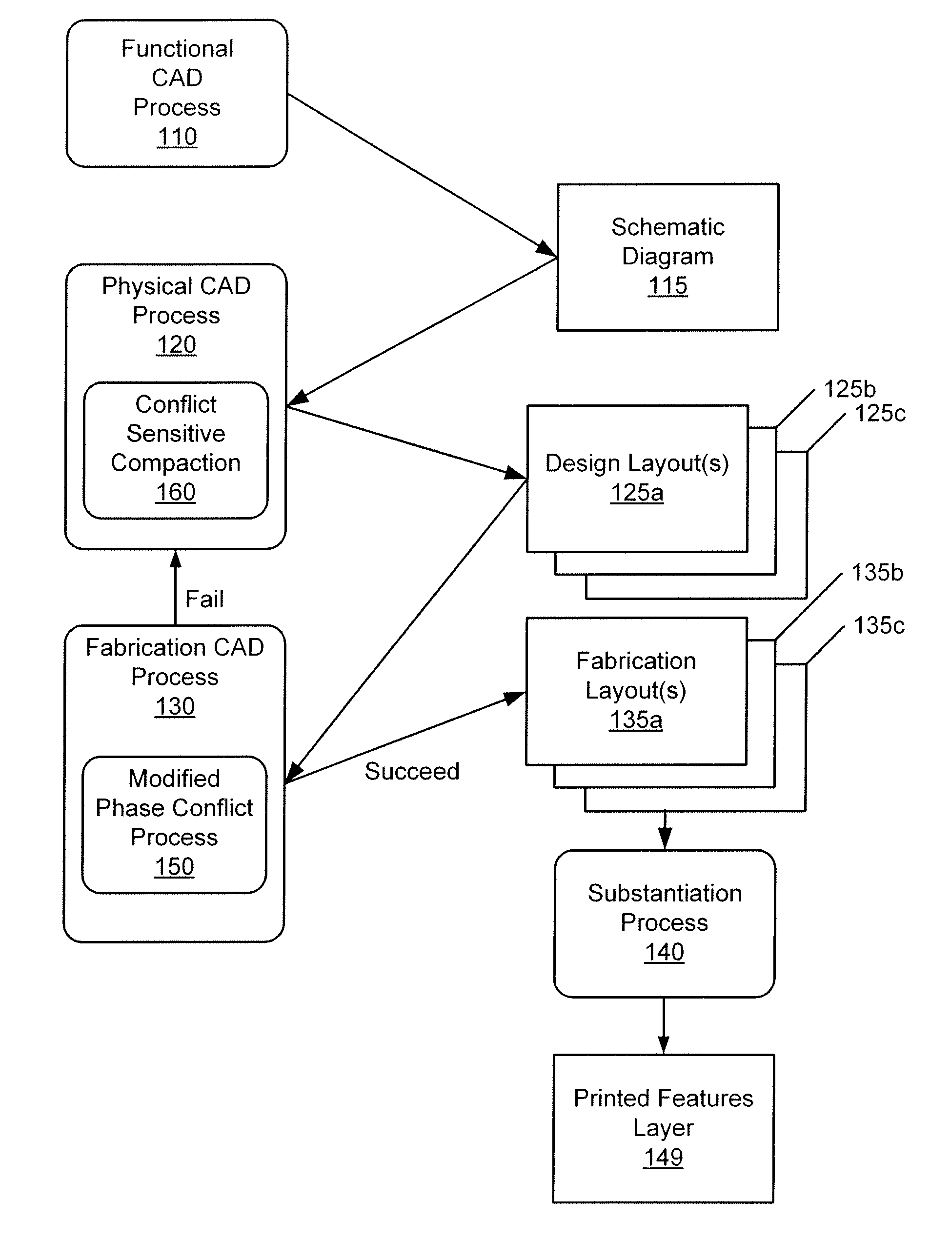
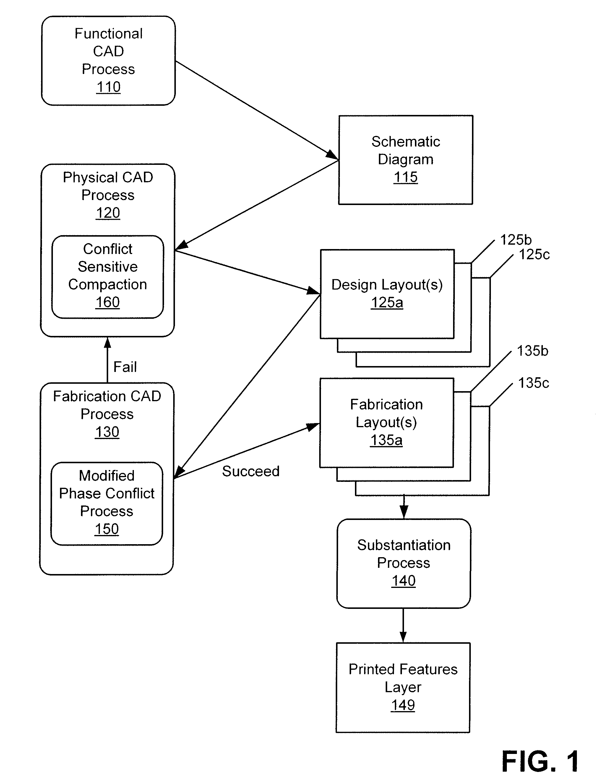
[0043] Techniques are provided for designing and fabricating printed features layers using a conflict sensitive compaction process 160 in the physical CAD process 120, and a modified phase conflict process 150 in the fabrication CAD process 130, as shown in FIG. 1. In the remainder of this section the relationship between the two techniques is described at a high level. In the following sections th...


PUM

PropertyMeasurementUnit
phaseaaaaaaaaaa
distanceaaaaaaaaaa
relative phaseaaaaaaaaaa

Abstract

Phase shifting allows generating very narrow features in a printed features layer. Thus, forming a fabrication layout for a physical design layout having critical features typically includes providing a layout for shifters. Specifically, pairs of shifters can be placed to define critical features, wherein the pairs of shifters conform to predetermined design rules. After placement, phase information for the shifters associated with the set of critical features can be assigned. Complex designs can lead to phase-shift conflicts among shifters in the fabrication layout. An irresolvable conflict can be passed to the design process earlier than in a conventional processes, thereby saving valuable time in the fabrication process for printed circuits.

Description

CLAIM OF PRIORITY [0001] This application claims priority to U.S. patent application Ser. No. 10 / 377,341-4038, filed Feb. 27, 2003 by Shao-Po Wu and Yao-Ting Wang and entitled “Incrementally Resolved Phase-Shift Conflicts In Layouts For Phase-Shifted Features” which claims priority of U.S. patent application Ser. No. 09 / 823,380-7393, filed Mar. 29, 2001 by Shao-Po Wu and Yao-Ting Wang, and entitled “Incrementally Resolved Phase-Shift Conflicts In Layouts For Phase-Shifted Features”, which in turn claims priority to U.S. Provisional Application Ser. No. 60 / 243,524, filed Oct. 25, 2000 by Shao-Po Wu, Yao-Ting Wang, Kent Richardson, Christophe Pierrat, and Michael Sanie, and entitled “Incrementally Resolved Phase-Shift Conflicts In Layouts For Phase-Shifted Features”. RELATED APPLICATIONS [0002] This application is related to U.S. patent application Ser. No. 09 / 823,146-8659, filed Mar. 29, 2001 by Yao-Ting Wang, Kent Richardson, Shao-Po Wu, Christophe Pierrat, and Michael Sanie, and en...

Claims


Application Information

Patent Timeline
Patent Type & Authority Applications(United States)
IPC IPC(8): G06F17/50G03F1/30
CPCG03F1/30G06F30/398G06F2119/18Y02P90/02
Inventor WU, SHAO-POWANG, YAO-TING
Owner SYNOPSYS INC
Why Eureka
Try Eureka