Directional geothermal energy system and method

a geothermal energy and directional technology, applied in the direction of mechanical power devices, machines/engines, mechanical equipment, etc., can solve the problems of increasing permeability, large gaps and increased permeability, and a large portion of geo-fluid is being continually lost,

Inactive Publication Date: 2007-10-25
MICKLESON D LYNN
View PDF6 Cites 76 Cited by
  • Summary
  • Abstract
  • Description
  • Claims
  • Application Information

AI Technical Summary

Problems solved by technology

Access to and capacity of these naturally occurring hydrothermal reservoirs is rather limited so that other portions of the earth's mass containing relatively hot dry rock are also being developed for energy production by another conventional geothermal approach using Hot Dry Rock (a.k.a.
The high pressure of the pumped fluid causes slippage between the natural fractures greatly increasing the gaps between the slipped portions of rock thereby greatly increasing permeability.
When the high fluid pressure is reduced or stopped, the fractures partially close back up, however, the fractures do not match up with each other as they had before the pumped fluid was injected, so much of the gaps and the increased permeability remain.
Unfortunately, the overall configuration (including shape, orientation, and internal structure) of an engineered geothermal reservoir is almost entirely dependent upon geologic conditions local to the vicinity of the reservoir.
Unfortunately, as the geo-fluid is circulated through the engineered geothermal reservoir, a portion of the geo-fluid is being continually lost due to such factors as retention of the fluid by the reservoir, gradual expansion of the reservoir, and leakage of the fluid out of the reservoir into rock volumes peripheral to the reservoir.

Method used


Image

  • Directional geothermal energy system and method
  • Directional geothermal energy system and method
  • Directional geothermal energy system and method

Examples


Embodiment Construction

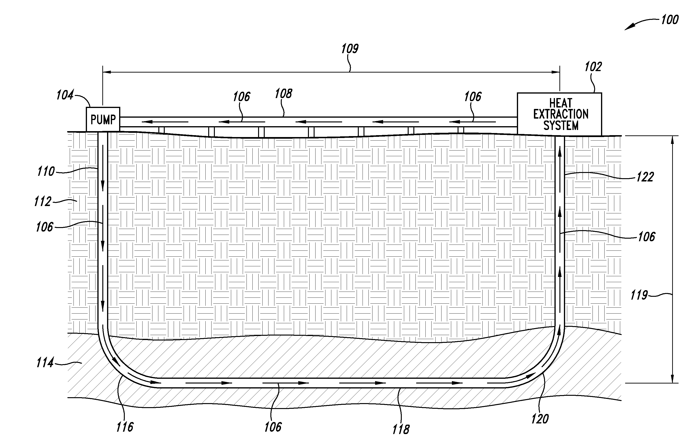
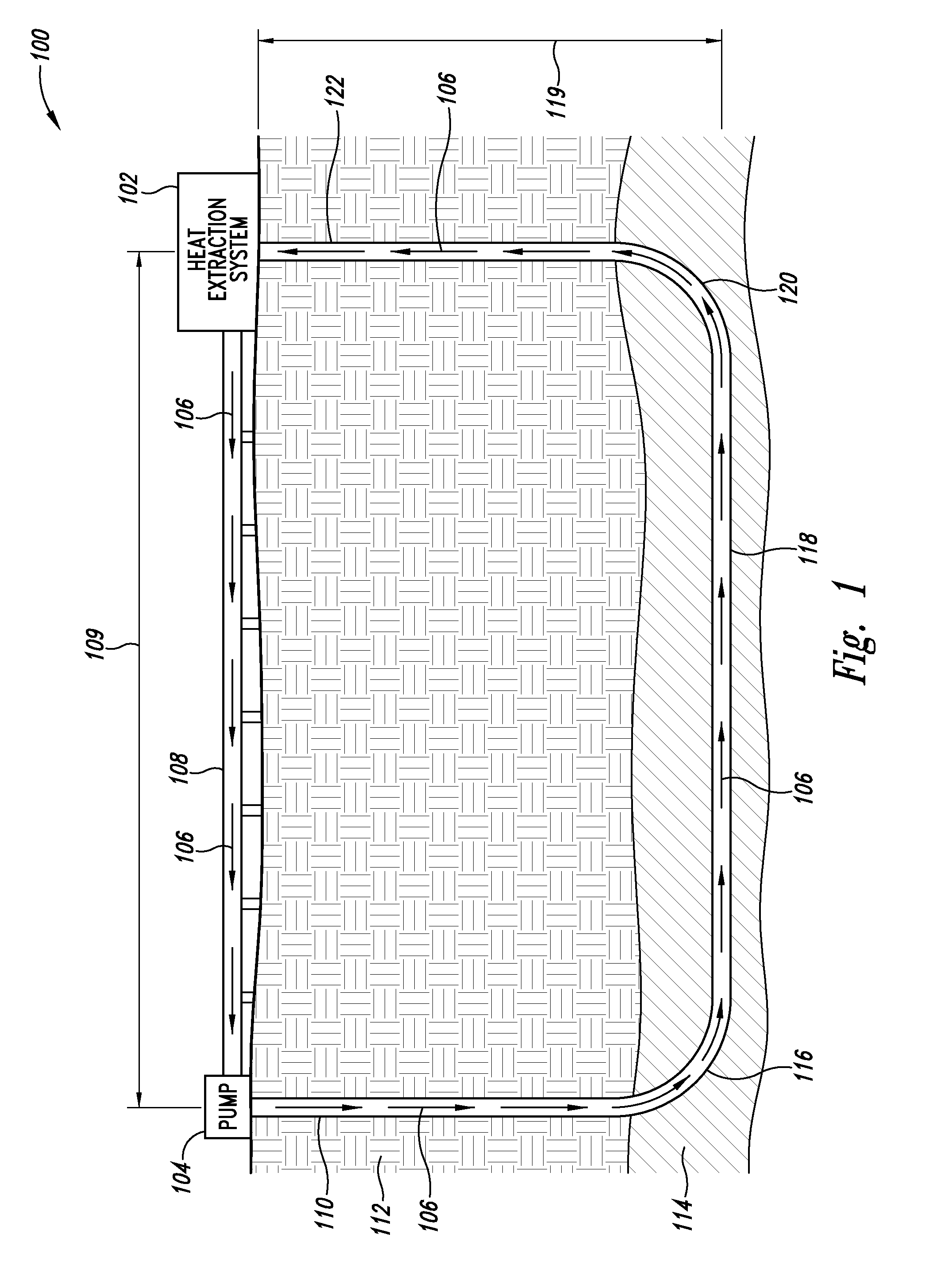
[0020]As discussed herein, a directional geothermal energy system and method helps to increase control in paths to be taken by geo-fluid flow through hot rock to create an enhanced engineered geothermal reservoir. Increased control of geo-fluid flow paths can further allow for construction of planned geo-fluid flow path networks to mine heat from particular hot rock resources. Overall configuration, including shape and orientation, of the geo-fluid networks may be planned with less dependence upon local geological characteristics than found in conventional methods.

[0021]The system uses directional drilling techniques to create a spanning borehole (shown with portions being substantially horizontal) extending between an injection borehole and a production borehole. The spanning borehole typically extends through hot rock for a distance on the order of kilometers to allow the geo-fluid flowing through the spanning borehole adequate transit time and surface contact to obtain sufficient...


PUM


Abstract

A directional geothermal energy system and method helps to increase control in paths to be taken by geo-fluid flow through hot rock to create engineered geothermal reservoirs and networks to mine heat from hot rock resources. The system uses directional drilling techniques to create a spanning borehole extending between an injection borehole and a production borehole. The spanning borehole typically extends through hot rock for a distance on the order of kilometers to allow the geo-fluid flowing through the spanning borehole adequate transit time and surface contact to obtain sufficient heat given a certain flow rate for the geo-fluid. In some implementations, multiple injection boreholes can supply geo-fluid to a single production borehole. Individual geo-fluid networks can be so sized, shaped, and located with respect to one another to form a collection of geo-fluid networks to mine heat from very large hot rock resources.

Description

CROSS REFERENCE TO RELATED APPLICATION(S)[0001]This application claims priority benefit of provisional application Ser. No. 60 / 745,376 filed Apr. 21, 2006.BACKGROUND OF THE INVENTION[0002]1. Field of the Invention[0003]The present invention is related to geothermal power generation systems.[0004]2. Description of the Related Art[0005]The earth contains so much heat that it has been estimated that less than 0.1% of the earth's mass is cooler than 100° C. As one descends into the earth's crust the temperature rises by approximately 1 degree Fahrenheit for every 100 feet of depth. A 5000 foot gold mine shaft is about 50 degrees above the surface temperature. Some areas of the earth can be mined for heat by conventional geothermal energy production techniques. Some of these areas of the earth have naturally occurring hydrothermal reservoirs with high temperature water and / or steam at shallow depths and / or at lower depths in natural fractures of basement rock or in sedimentary rocks with...

Claims


Application Information

Patent Timeline
Patent Type & Authority Applications(United States)
IPC IPC(8): F03G7/00
CPCF01K23/02Y02E10/10F03G7/04F01K25/106F24T10/20F24T2010/53
Inventor MICKLESON, D. LYNN
Owner MICKLESON D LYNN
Why Eureka
Try Eureka