Petroleum extraction from hydrocarbon formations

a hydrocarbon formation and petroleum extraction technology, applied in the direction of drinking water installation, borehole/well accessories, construction, etc., to achieve the effect of improving fluid displacemen

Inactive Publication Date: 2009-11-24
CRICHLOW HENRY B
View PDF9 Cites 32 Cited by
  • Summary
  • Abstract
  • Description
  • Claims
  • Application Information

AI Technical Summary

Benefits of technology

[0057]An object of this invention is to provide an improved process for recovery of heavy oils and similar hydrocarbons from subterranean formations by exploiting the advantages provided by gravity drainage in the displacement process of heavy oils in porous formations using steam or combustion driven displacement processes. The use of a modified single well bore, with a downward, lateral and upward section, the uniwell™, along with a collection cavity connected to a producer well system, has several engineering benefits including cost reduction, better fluid displacement and more engineering control and economic recovery of the injection and oil recovery process.
[0061]Another specific objective is to provide a means to considerably reduce the distance the heated oil has to move from the steam injection point to be produced in the wellbore through the producing formations.
[0064]Another specific objective is to allow the steam to replace oil and to pressure up the steam bank at the top, which helps to displace low viscosity, heated oil downwards along the interface of steam / cold reservoir oil to the producing perforations where there exists a pressure sink because oil is being removed during production.
[0065]Another specific objective is to use the accumulated oil in the lateral and upward portion of the wellbore to act as an U-tube device, which behaves similarly to a P-trap in a household drain, allowing the steam to remain on the injector side of the wellbore and maximize growth of the steam zone in the reservoir where it is more effective.
[0066]Another specific objective is to use the produced oil, which accumulates in the lateral and upward portion of the wellbore to act as a backpressure system such that the steam bank is prevented from break through by flowing down the wellbore.

Problems solved by technology

It is technically difficult to visualize the steam entering a cold highly viscous formation while a completely open wellbore is available for fluid flow away from the formation.
This situation is not only physically impossible but it thermodynamically impossible for the hot fluid to flow “against the pressure gradient”.
This type of downhole flange connection is extremely difficult if not impossible to implement in current oilfield practice.
This technology, while theoretically possible is operationally difficult to hit such a small underground target, i.e the axial cross-section of a typical 8-inch wellbore using a horizontal penetrating drill bit.
Very few of these prior art systems have been used in the industry with any success because of their technical complexity, operational difficulties, and being physically impossible to implement or being extremely uneconomical systems.
Secondly, the large distance between the top of the formation and the bottom of the formation will cause condensation of the drive steam allowing essentially hot water to be produced at the bottom with low quality steam, both fluids being re-circulated back to the surface.
In addition, the mechanism to heat the near wellbore can only be based on conductive heat transfer through the steel casing.
There is ineffective heat transfer since there is no direct steam contact with the formation rock in which latent heat transfer to formation fluids and rock can occur, this latent heat being the major heat transport system.
This problem has continued to baffle the contemporary and prior art with possibly the only exception being the SAGD patent which uses two horizontal wells closely juxtaposed in a vertical plane.
Even this SAGD approach has inherent difficulties in initiating the hot oil flow between the two wellbores.
This flow ratio is based directly on the viscosity ratios.(3) the inability of the methods to prevent steam bypass, without some type of seal mechanism, of this extremely highly mobile injected fluid directly from the injector source towards the producing sink.(4) the inability of the method to form and maintain a viable communication zone from the steam zone or chamber to the producing sink while preventing bypass and early breakthrough of steam.(5) the inability of the process to utilize the gravity drainage effects created by the low density of the hot steam compared to condensed water and hot oil.(6) the inability of the process to heat the formation effectively by physical contact between the steam and the rock formation such that latent heat, the major source of steam heat energy, can be transferred to the rock and hydrocarbons efficiently.(7) the requirement of long lead times of months to years of hot fluid injection, before there is any production response of the displaced oil.(8) finally the use of overly complex equipment of questionable operational effectiveness to implement the process in the field.

Method used


Image

  • Petroleum extraction from hydrocarbon formations
  • Petroleum extraction from hydrocarbon formations
  • Petroleum extraction from hydrocarbon formations

Examples


Embodiment Construction

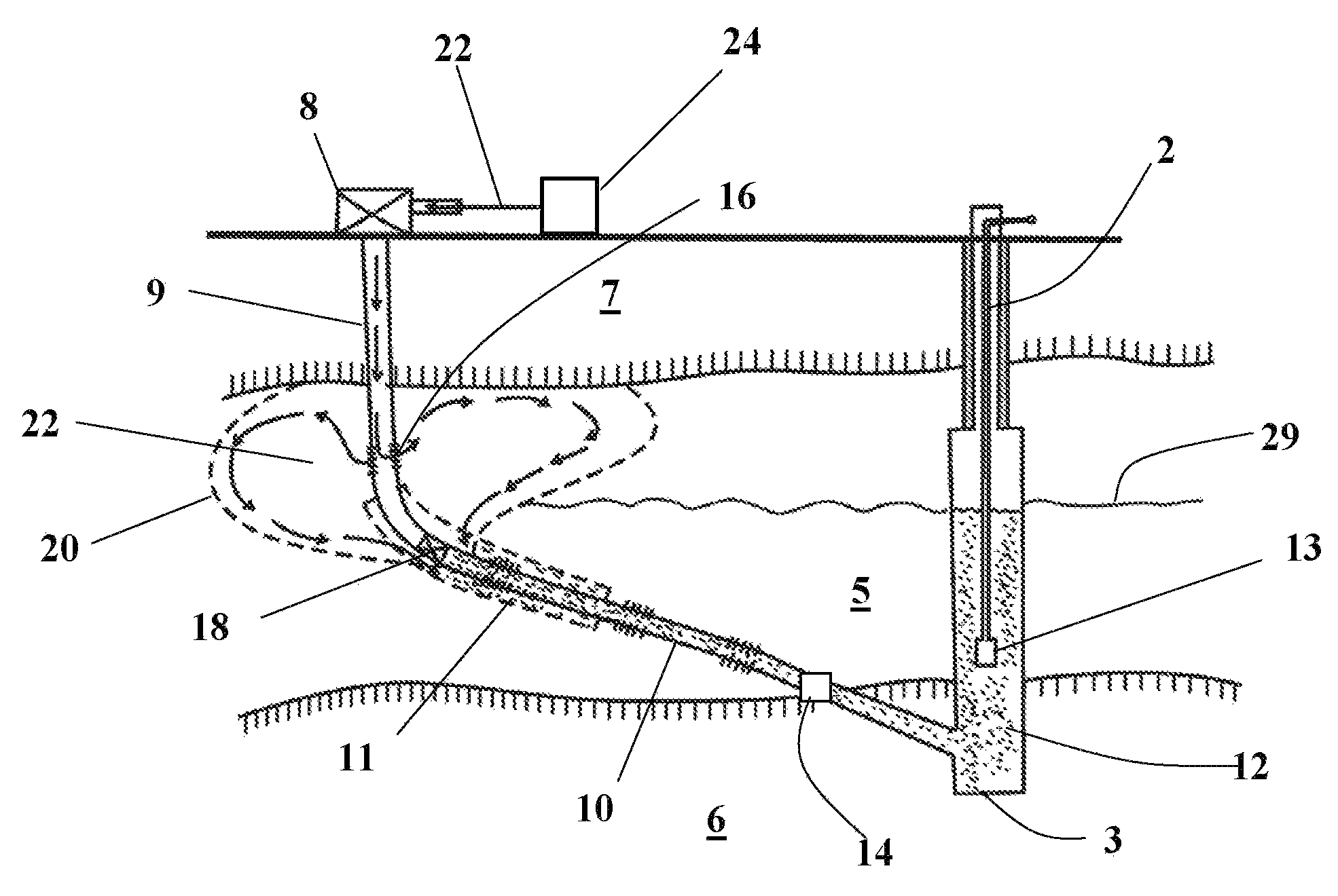
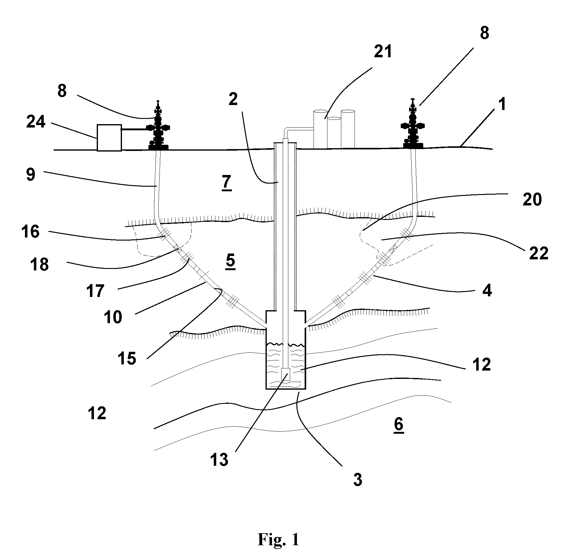
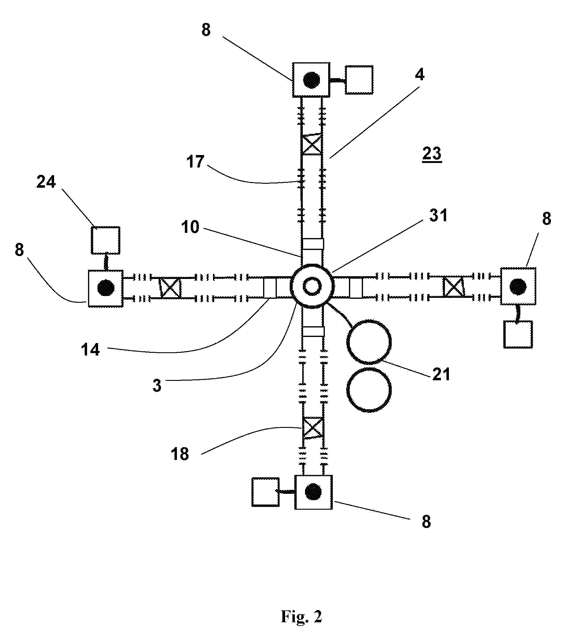
[0086]Referring now to the drawings the new invention process is described as follows. Referring to FIG. 1 and FIG. 10, a central wellbore 2 is drilled from the surface of the ground 1 down to and passing through the hydrocarbon bearing formation 5 as shown in step 100. The central wellbore is under-reamed by using a reamer tool to provide a large cavity 3 up to as much as 8 feet in radius and several feet deep as indicated in step 101. Oilfield tools provided by Ref. 2. are capable of performing this operation routinely. After the central well 2 is drilled and under-reamed it forms a production cavity 3 at its bottom. This production cavity can hold several hundred barrels of hot oil and condensed water. For example., a 6-foot radius cavity that is 20 feet high can hold in excess of 1,000 barrels of fluid. This volume can be about a one-week fluid production volume from a typical shallow stimulated steam well. As shown in step 102 a series of uniwells 4 are drilled from the surface...


PUM


Abstract

Recovery of viscous hydrocarbon by hot fluid injection from subterranean formations is assisted by using a specially designed and under-reamed vertical well to form a central production cavity; combined with a plurality of specially perforated horizontal wells drilled from the surface down to the producing formation, and then drilled laterally to intersect and be operatively connected to the central production well cavity. These continuous horizontal uniwells™ behave as single wells with two wellheads, each with multiple injection-production perforation pairs, between which the controlled flow of hot oil via a specialized annular communication zone. The production process is controlled by modulating the hot oil flow where the wellbore fluids act as a hydraulic “P-trap” seal limiting steam bypass. The hot displaced oil is allowed to drain from the lateral horizontal wells in to the central collection cavity.

Description

CROSS REFERENCE TO RELATED APPLICATIONS[0001]This application claims priority from Disclosure Document 589,546 by Dr. Henry Crichlow filed on Nov. 7, 2005 and Provisional Patent 60 / 763,844 filed on Feb. 1, 2006 by Dr. Henry Crichlow.INTRODUCTION[0002]This invention relates generally to a new technology application and a new type of oil well for recovery of hydrocarbons from subterranean oil bearing formations.[0003]This invention is related to prior filings by the same applicant, pertaining to the overall recovery of hydrocarbons from subterranean oil formations. The technology involves the novel use and application of equipment and techniques in which horizontal wells are drilled from the surface down to and across an oil bearing formation and back up to the surface, in a manner similar to that of drilling under a river crossing when laying pipelines across country. This new type of horizontal well is called a Uniwell™ because it has two surface wellheads one at each end of the axi...

Claims


Application Information

Patent Timeline
Patent Type & Authority Patents(United States)
IPC IPC(8): E21B43/24
CPCE21B43/305E21B43/24
Inventor CRICHLOW, HENRY B
Owner CRICHLOW HENRY B
Why Eureka
Try Eureka