Connector System

a technology of connecting rods and connecting rods, which is applied in the direction of machine/engine, machine feed system, fuel injection apparatus, etc., can solve the problems of changing stroke, compressive or flexural load, and the clamping effect of the clamping claw on the fuel injection valv

Inactive Publication Date: 2007-10-25
ROBERT BOSCH GMBH
View PDF23 Cites 15 Cited by
  • Summary
  • Abstract
  • Description
  • Claims
  • Application Information

AI Technical Summary

Benefits of technology

[0005] The connector system according to the exemplary embodiment of the present invention for a fuel injection valve to be inserted into a receiving orifice into a cylinder head, for connection to a fuel distributor line that encompasses a connector to a tubing line leading to a fuel reservoir, having a connecting part for connection to the tubing line and having the characterizing features of the main claim, has, in contrast, the advantage that no excessive transverse forces that damage the valve are effective upon installation onto the fuel injection valve.
[0006] The tolerance compensation necessary therefor is carried out on the one hand at the connecting part to the tubing line, by the fact that the ball-shaped end part according to the exemplary embodiment of the present invention can be moved, prior to tightening of the coupling nut, perpendicular to the plane in which the tubing line is located, and thus makes possible installation without transverse forces. A motion of the tubing line along its extent, caused by axial forces, causes an...

Problems solved by technology

A particular disadvantage of this mounting apparatus is the clamping effect of the clamping claw on the fuel injection valve.
The energy flow produced in the fuel injection valve results in deformations and thus in changes in the stroke of the valve needle to the point of jamming, and in a compressive or flexural load on the housing parts, which are generally thin-walled and welded to one another at multiple locations.
Any mounting action, for example by way of a support collar, furthermore results in an enlargement of the radial extent of the fuel injection valve and thus in an increas...

Method used


Image

  • Connector System
  • Connector System
  • Connector System

Examples


Embodiment Construction

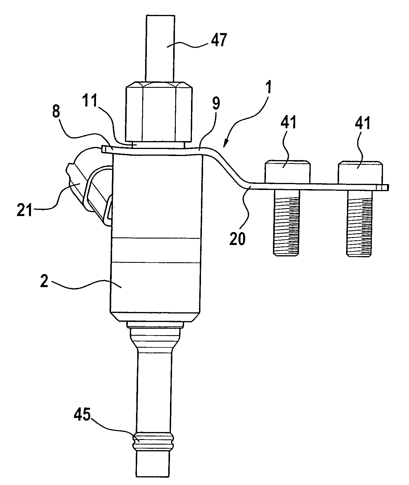
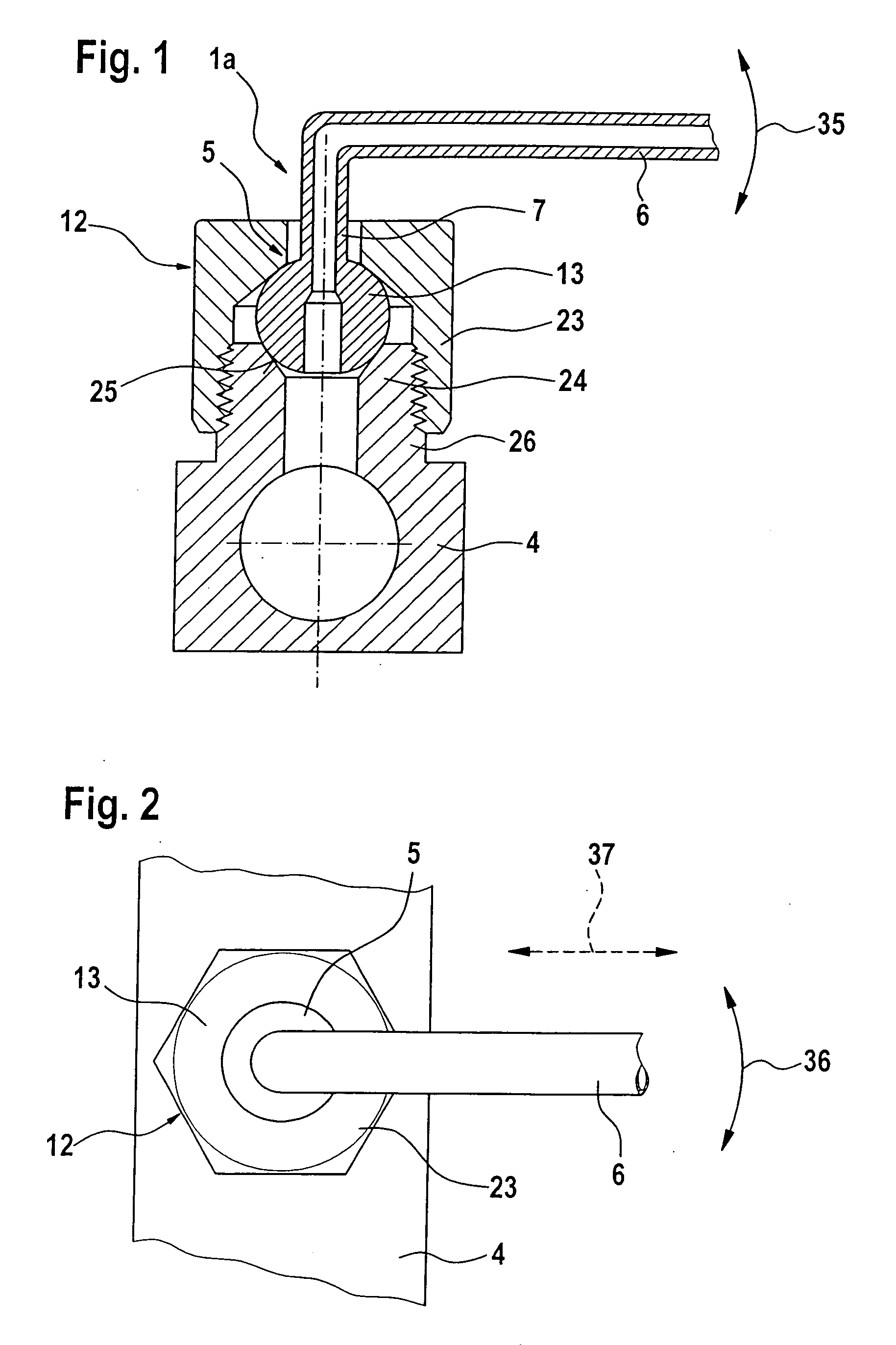
[0018]FIG. 1 is a side view, in a sectioned depiction, of a portion of a connector system 1, 1a according to the exemplary embodiment of the present invention for connecting a fuel distributor line 4 to a tubing line 6 leading to a fuel reservoir (not depicted further).

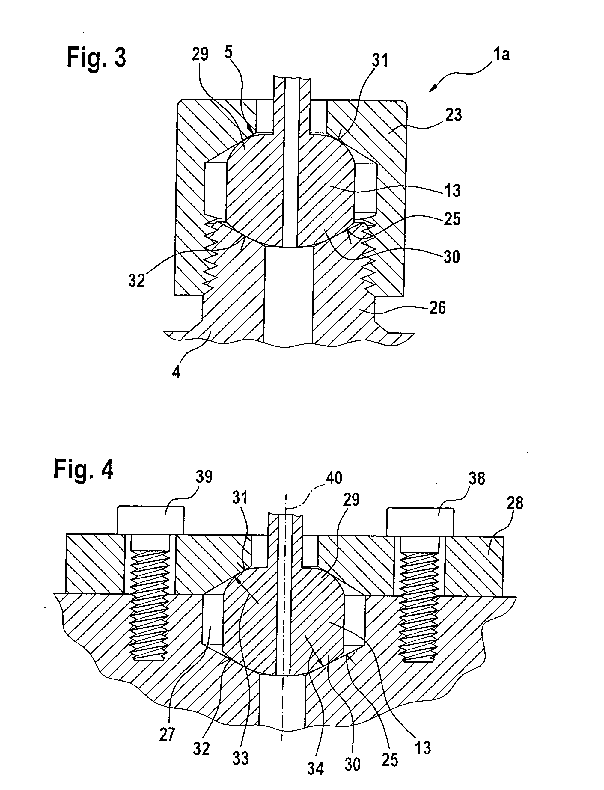
[0019] Connector system 1, 1a according to the exemplary embodiment of the present invention, for a fuel injection valve 2 to be inserted into a receiving orifice in a cylinder head for connection to a fuel distributor line 4 that encompasses a connector 5 to a tubing line 6 leading to a fuel reservoir, having a connecting part 7 for connection to tubing line 6, is characterized in that a holddown claw 8 has at its first end 9 an elongated opening 10 for reception of a connector piece 11, connected to the inflow-side end of the fuel injection valve, to fuel distributor line 4; and that connecting part 7 to tubing line 6 has a tube screw fitting 12 having an end piece 13.

[0020] End piece 13, which can be embodied as ...


PUM


Abstract

A connector system, free of transverse forces, for a fuel injection valve to be inserted into a receiving orifice into a cylinder head for connection to a fuel distributor line that encompasses a connector to a tubing line leading to a fuel reservoir, has a connecting part for connection to the tubing line. The connector system includes a holddown claw having an elongated opening that completely surrounds the fuel injection valve but allows for a tolerance compensation in the direction of the longitudinal axis of the holddown claw, and provides that the connecting part to the tubing line leading to the fuel reservoir has a tube screw fitting having an end piece. The end piece is embodied so that before the tubing line is screwed down onto the fuel distributor line, it can be moved for tolerance compensation, in a seat on the inflow-side end of the fuel distributor line, in two directions perpendicular to the extent of the tubing line.

Description

FIELD OF THE INVENTION [0001] The present invention relates to a connector system for a fuel injection valve to be inserted into a receiving orifice into a cylinder head. BACKGROUND INFORMATION [0002] The German patent document DE 101 12 665 A1 discusses a mounting apparatus for mounting a fuel injection valve for direct injection of fuel into the combustion chamber of an internal combustion chamber, which apparatus encompasses a holddown that is slipped onto the fuel injection valve, the holddown being embodied as a flat component and being braced against a sleeve, fitting around the fuel injection valve, that serves for tolerance compensation upon installation of the fuel injection valve. The holddown is tightened with the aid of a corresponding tool sufficiently firmly that the fuel injection valve is not pushed out of the cylinder head by the pressure existing in the combustion chamber of the internal combustion engine. [0003] A particular disadvantage of this mounting apparatus...

Claims


Application Information

Patent Timeline
IPC IPC(8): F02M61/14
CPCF02M55/005F02M61/14F02M55/02
Inventor SCHEFFEL, MARTINECKBAUER, ANDREAS
Owner ROBERT BOSCH GMBH
Why Eureka
Try Eureka